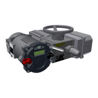
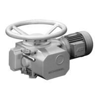
Operating instructions for actuators type AB with SMARTCON control unit
OM-ENGLISH-CSC-V2.08-2019.11.07 19 Technical data
Current range: . . . . . . . . . . . . . . . . . . . . . . . . . . . . . . . . . . . . . . . . . . . . . . . . . 0-20,5mA
Resolution: . . . . . . . . . . . . . . . . . . . . . . . . . . . . . . . . . . . . . . . . . . . . . . . . . . . . .10Bit
Accuracy: . . . . . . . . . . . . . . . . . . . . . . . . . . . . . . . . . . . . . . . . . . . . . . . . . . . . . . 0,5%
Max load: . . . . . . . . . . . . . . . . . . . . . . . . . . . . . . . . . . . . . . . . . . . . . . . . . . . . . . 600 Ohm
Reference ground is the common ground of the controller and the auxiliary voltage (see section 19.5).
19.5 Auxiliary voltage input and output
Input voltage range (auxiliary voltage input): . . . . . . . . . . . . . . . . . . . . 20-30VDC
Maximum current consumtion(auxiliary voltage input): . . . . . . . . . . 320mA
Maximum current consumption in power-save mode . . . . . . . . . . . . 100mA
(auxiliary voltage input):
Output voltage (auxiliary voltage output): . . . . . . . . . . . . . . . . . . . . . . . typ. 22V
Max output current (auxiliary voltage output): . . . . . . . . . . . . . . . . . . . 150mA
Resistance of ground potential vs. body: . . . . . . . . . . . . . . . . . . . . . . . typ. 100kOhm
Capacitance of ground potential vs. body: . . . . . . . . . . . . . . . . . . . . . . typ. 400nF
Voltage of ground potential vs. body: . . . . . . . . . . . . . . . . . . . . . . . . . . . max. 40Vs
Fuse: . . . . . . . . . . . . . . . . . . . . . . . . . . . . . . . . . . . . . . . . . . . . . . . . . . . . . . . . . . 500mA träge
(Littelfuse 454 NANO
2
Slo-Blo
R
)
Ground potential is the common ground of the controller and the analogue inputs and outputs.
The auxiliary voltage output can be set by the menue P6.5 (see capter 7.5, page 27).
The power-save mode is defined as follows:
• No power supply (the controller is powered exclusively through the 24V auxiliary voltage input).
• The lithing of the LCD display switches off automatically
• No additional hardware options available (Profibus Interface, DeviceNet interface, relay board, etc. . . ).
• Binary outputs and the mA output are not enables; when activating, the respective currents must be
added to the total current.
19.6 Mechanic reversing starters
By default the motor with a mechanical reversing contactor is switched three-pole. The mechanical reversing
contactor is both electrically and mechanically interlocked to prevent cross circuits.
Depending on the engine size results in the following assignments:
size Typ power of the motor (with 400V 3-phase current)
open-loop control
(operational mode S2)
closed-loop control
(operational mode S4)
mW4 K09 3kW 1,5kW
mW5 K12 5,5kW 3kW
mW7 D18 7,5kW 5,5kW
mW11 D25 11kW 7,5kW
mW22 D38 22kW 11kW
The mechanical life (switching cycles) of the reversing starter can be roughly estimated with the help of the
following diagram and the rated current (motor current):
55