5 Commisioning
Operating instructions for actuators type AB with SMARTCON control unit
OM-ENGLISH-CSC-V2.08-2019.11.07
5 Commisioning
Before commissioning, please ensure the actuator is correctly assembled and electrically connected. (see
section 4, page 9)
CAUTION: Remove silica gel from the connection compartment
5.1 General
textbfCAUTION: During commissioning and after every disassembly of the actuator, you have to
make the mechanical preadjustment (see sction 5.3, page 13), adjust the mechanical position indi-
cation (see section 5.4, page 14), adjust the additional components (see scetion 5.5, page 14) and
adjust the end positions (see section 5.7, page 14).
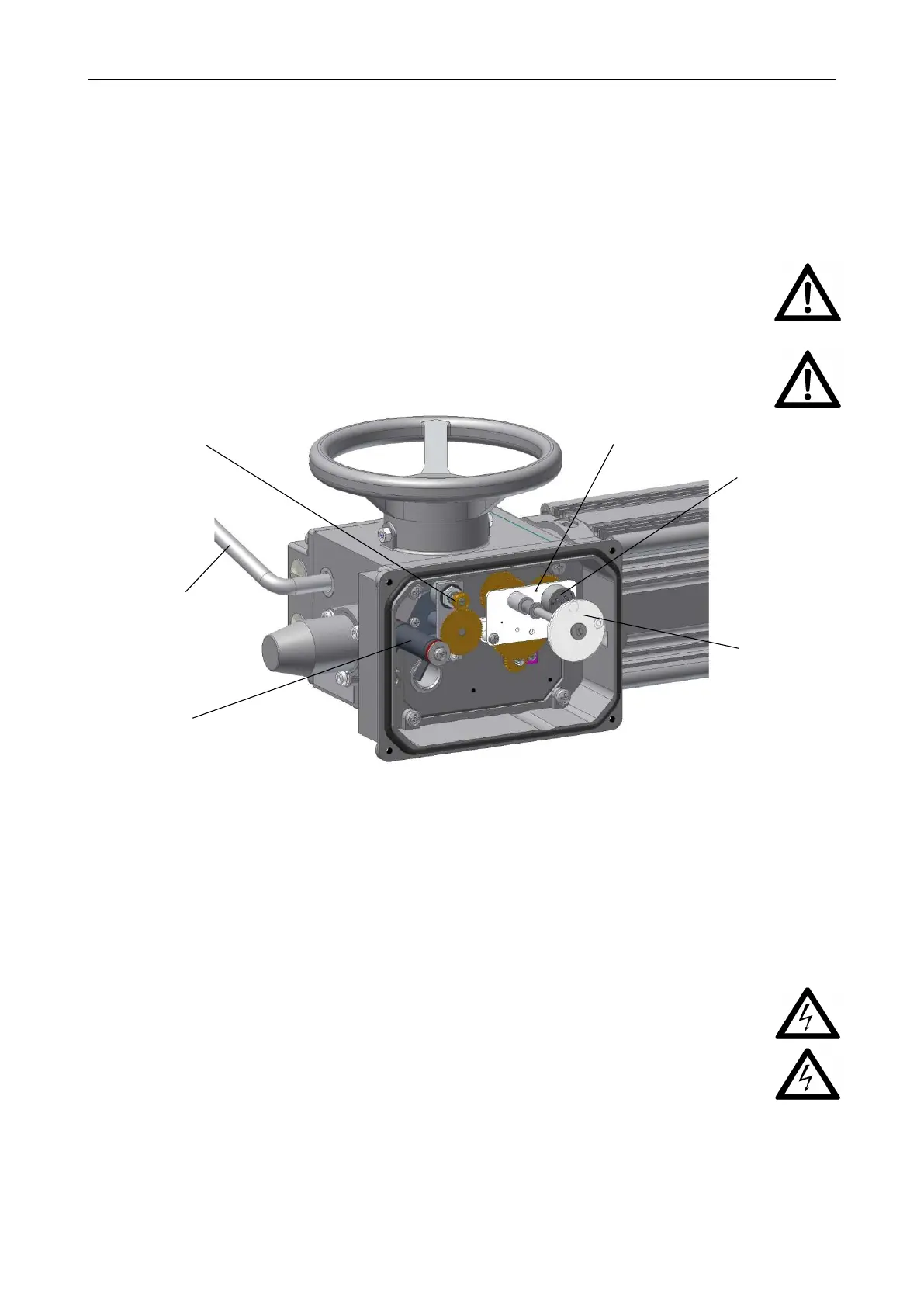
ATTENTION: The torque unit is adjusted at work and must not be changed.
Figure 14: 1. . . torque unit , 2. . . hand lever, 3. . . heating resistor - Attention: HOT!!!, 4. . . gearing of travel
unit, 5. . . potentiometer for travel sensing, 6. . . mech. position indicator (option)
5.2 Switching the actuator to manual operation
The actuator is switched to manual operation by moving the hand lever (see Figure 15 u. 16) by approximately
15
◦
, and by simultaneously turning the hand wheel. The lever remains in this position and will be switched
back automatically as the motor starts up.
WARNING:
•
When switching to manual operation, the actuator’s automatic interlock is deactivated, that
means that the driven valve must not initiate reverse torque to the output shaft of the actuator!
•
Switching back to motor operation is made automatically as the motor starts up. It must not
be undertaken with the hand lever!
• Only switch to manual operation when the motor is idle!
• Hand lever has a slewing angle of approximately 15
◦
, therefore release the hand lever immediately
upon activation!
Labels on the actuator:
12
 Loading...