2 General
Operating instructions for actuators type AB with SMARTCON control unit
OM-ENGLISH-CSC-V2.08-2019.11.07
2.4 Protection class
Actuators with three-phase motors are standardly equipped with the IP 66 protection system (according to DIN-
Standard 40050). Explosion-proof actuators and actuators with plugs are furnished with the IP 65 protection
system. Exceptions are the AC, DC and brake-motor actuators as well as those for other protection systems
made to special order.
CAUTION: The protection class specified on the nameplate is only effective when cable
glands also provide the required protection class, the cover of the connection compartment
is carefully screwed and the mounting position (see section 2.5, page 6) is observed.
We recommend metallic screwed cable glands with a metrical thread. Furthermore, cable inlets
not be needed must be closed with screw plugs. On explosion-proof actuators cable glands with
protection class
EEx e according EN60079-7 must be used. After removing covers for assembly purposes or adjustment
work, take special care upon reassembly so that seals are not damaged and remain properly fastened. Im-
proper assembly may lead to water entrances and to failures of the actuator.
Allow a certain sag in the connector cables before reaching the screwed cable glands so that water can drip
off from the connector cables without running to the screwed cable glands. As a result, forces acting on the
screwed cable glands are also reduced. (see section 2.5)
2.5 Mounting position
In principle, the installation position is irrelevant. However, based on practical experience, it is advisable to
consider the following for outdoors use or in splash zones:
• Mount actuators with cable inlet facing downwards
• Do not arrange the motor so that it hangs downwards
• Ensure that sufficient cable slack is available
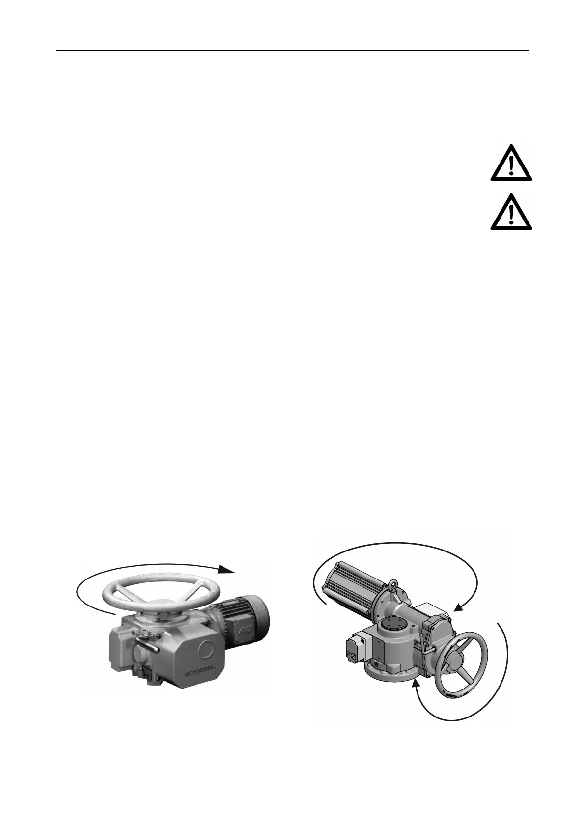
2.6 Direction of rotation
Unless specifically ordered otherwise, the standard direction is (see Figure 7 and Figure 8):
Clockwise rotation = Close
Counter-clockwise rotation = Open
Clockwise rotation of the actuator is given when the output shaft turns counter clockwise when looking on the
output shaft.
Figure 7: AB3 - AB80
Figure 8: AB100 - AB500
All data in these operating instructions refer to the standard rotating direction.
6
 Loading...