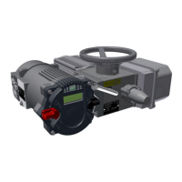
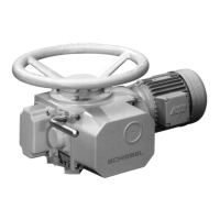
Operating instructions for actuators type AB with SMARTCON control unit
OM-ENGLISH-CSC-V2.08-2019.11.07 6 Control unit
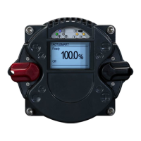
6.3.1 Operation mode
Use the selector switch (red) to determine the various operating states of the actuator. In each of these posi-
tions, it is possible to block the switch by means of a padlock and thus protect the actuator against unauthorized
access.
The selector switch has the following positions:
OFF
The actuator can be neither operated via the remote control nor via the
control switches of the controller.
Local
It is possible to operate the actuator by motor via the control switch. Control
via the remote inputs may be possible with appropriate configuration
(superimposed control commands, emergency commans)
Remote
The actuator is ready to process control commands via input signals. The
control switch for the motor operation of the actuator is not enabled.
Besides defining the operational status, the selector switch is used in configuration mode to confirm or cancel
parameter inputs.
Depending on the selector switch position, the control switch performs different functions:
Selector switch in the
OFF position:
The control switch is used to scroll up or down the menu according to internal
symbolism. From the neutral position towards you reach the status and
history data areas. Towards the symbols you reach the parameter menu.
Here, the selection switch either confirms or rejects the current input
according to associated symbolism.
Selector switch in the
REMOTE position :
The control switch gives you access to status, history data and parameter
area.
Selector switch in the
LOCAL position :
With the control switch, the actuator can be operated by motor. You may also
operate the actuator in inching and self-hold mode. Switches are
spring-loaded to snap back automatically into their neutral position. (To
confirm a control command, the control switch must be pushed all the way
into its mechanical locking position.)
6.3.2 Configuration
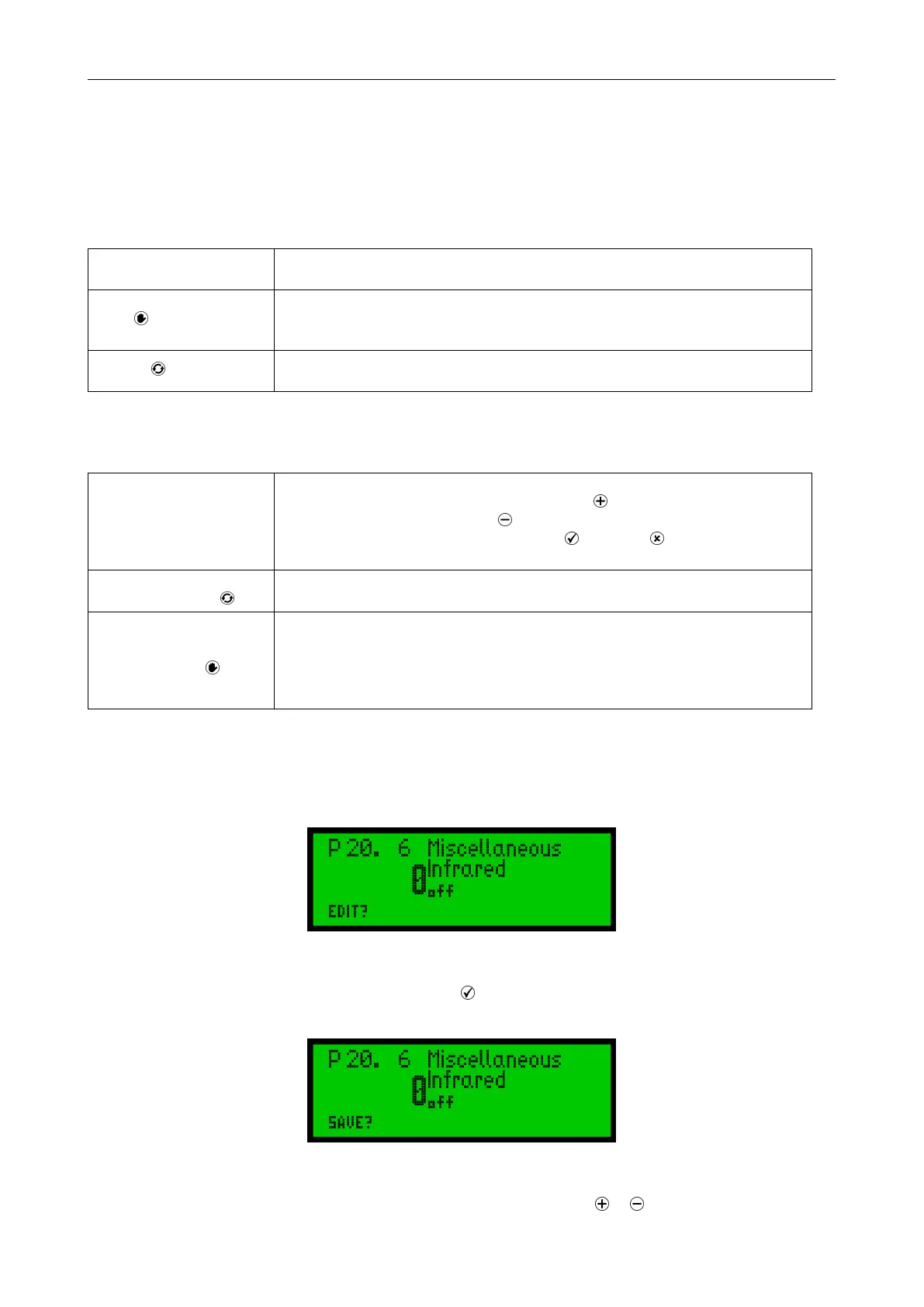
In principle, all parameters are shown as numbers in the corresponding parameter point. From the actuator
menu, use the control switch to access different menu points. The lower left corner of the display shows the
"EDIT" option.
Figure 47
Confirm the selector switch (with a slight flip towards , (see Figure 34, page 17 to Figure 36, page 17) to
change the selected parameter. To confirm this input readiness, the display changes from "EDIT" to "SAVE".
Figure 48
Use the control switch towards to the characters to change the parameter. or (see Figure 43 til Figure 46,
21
 Loading...