5 Commisioning
Operating instructions for actuators type AB with SMARTCON control unit
OM-ENGLISH-CSC-V2.08-2019.11.07
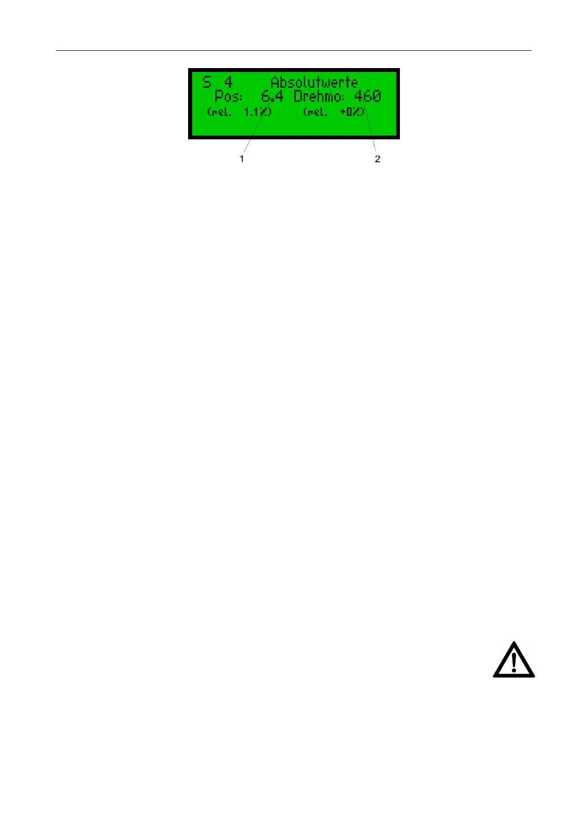
Figure 20: 1. . . absolute value of the position unit, 2. . . value for the torque unit (is factory adjusted)
For the set up of the end positionsl see section 5.7, page 14.
The abobe transmitter gear is made according to the customer’s specifications. If another travel of the actuator
is necessary, a new transmitter gearbox can be supplied.
5.4 Adjustment of the mechanical position indication (Option)
The adjustment of the mechanical position indication should be done together with the mechanical pre-setup.
Vorgehensweise:
• Switch with the hand lever to manual operation (see section 5.2, page 12) and turn the actuator to the
next end position.
• Remove cover of the signalling unit
• turn Indicator slide according below end position:
– when the actuator in in the closed position: Display with the filled circle
– when the actuator is in the open position: Display with the circle
• move the actuator to the other end position and turn the other Indicator slide. It is necessary that you
hold the second slide in its earlier set position.
• Check the clamping screw
• Close cover of the signalling unit. Take special care upon reassembly so that seals are not damaged and
remain properly fastened
5.5 Additional components (Option)
Possibly installed additional components have to be set-up according their separately supplied technical de-
scriptions.
5.6 Parameterize of the SMARTCON control unit
After finishing the pre-setup of teh actuator (see section 5.3, page 13) all further settings can be done via the
SMARTCON interface.
WARNING: It is absolutely necessarily to control the torque settings of the actuator and to teach in
the end positions of the travel.
5.7 End limit setting
A detailed description of the operation of the SMARTCON control unit can be found in section 6.3, page 20.
5.7.1 End limit OPEN
Set the selector switch and control switch to the centre position.
14
 Loading...