Assembly and settings
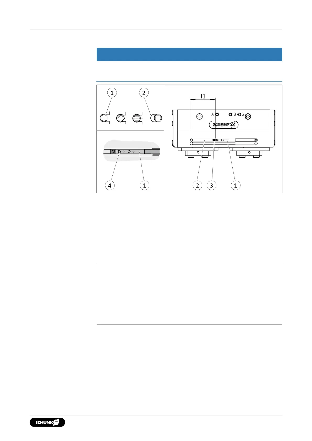
5.5.9 Mounting analog MMS 22-A magnetic switch
NOTICE
Risk of damage to the sensor during assembly!
• Observe the maximal tightening torque.
1. Adjust the T-nut(3) to dimension l1, }5.5.2 [
/
31].
2. Slide the sensor(1) over the insertion pocket into the groove
(2) according to the shown orientation of the cable outlet until
the sensor (1) rests against the T-nut (3).
3. Secure the sensor (1) using the set-screw (4).
Tightening torque: 10Ncm
4. Adjust sensor (1), see Translation of Sensor Assembly and
Operating Manual.
NOTE
• The installation position and orientation described above
ensures optimum operation of the sensor, especially in the two
peripheral areas.
• The function of the sensor in the two peripheral areas is not
ensured if the lower groove is used or the sensor is inserted
offset by 180°.
4102.00 | PGL-plus-P | Assembly- and Operating Manual | en | 1508050