Assembly and settings
5.5.2 Setting dimensions for magnetic switches
The sensors can be pushed into the groove from the right or left.
Depending on the side of the cable outlet, there are different
setting dimensions.
Left cable outlet
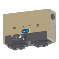
PGL-plus-P 10–13
PGL-plus-P 10–13: Setting dimension I1, cable outlet left
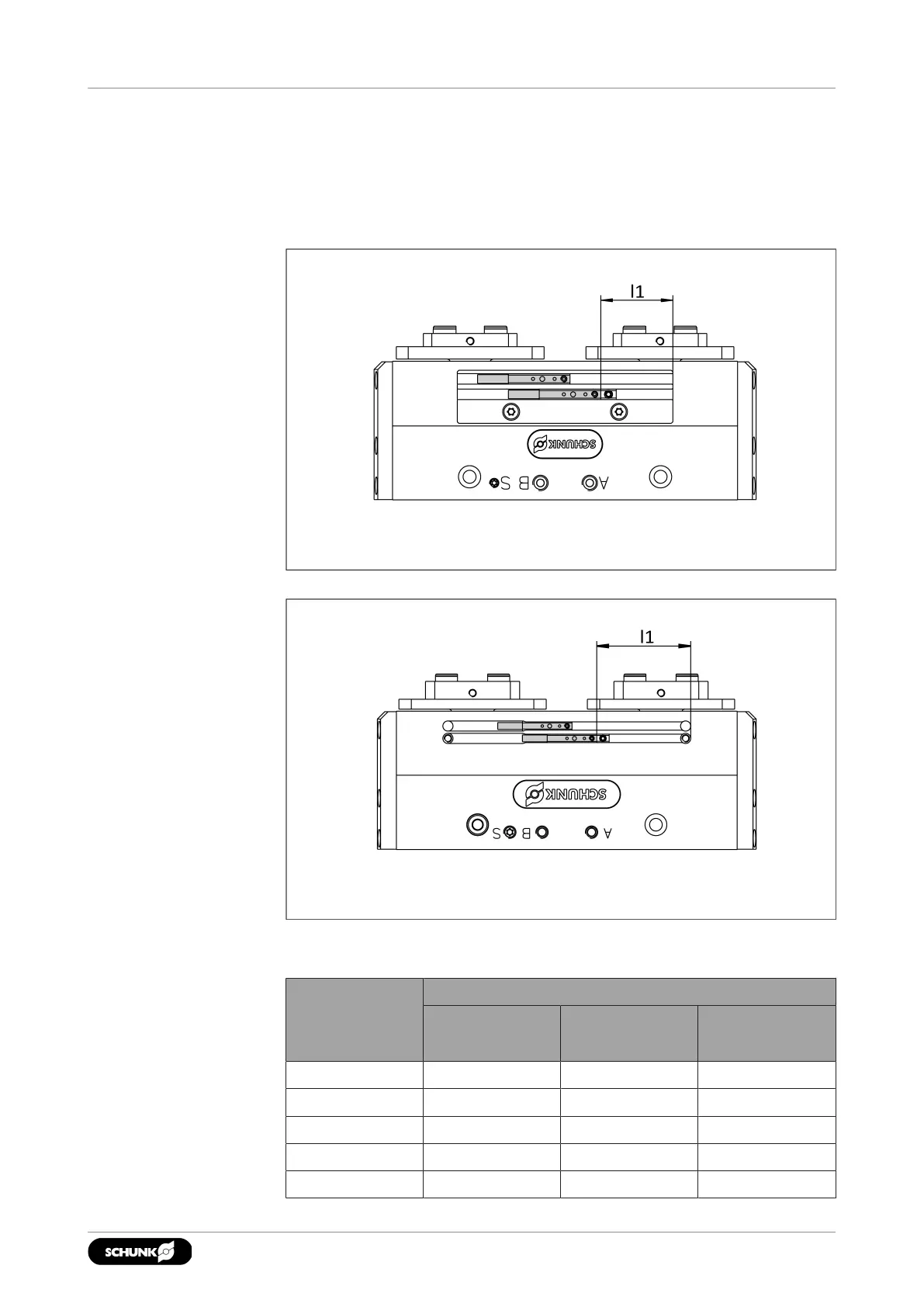
PGL-plus-P 16–25
PGL-plus-P 16–25: Setting dimension l1, cable outlet left
Setting dimension l1 - cable outlet left
Size Setting dimensionsl1[mm]
MMS22-PI1
MMS22-PI2
MMS22-A MMS22-IOL
10 17.8 19.8 18.6
13 18.4 20.4 19.8
16 33 35 33.8
20 45.2 47.2 45.6
25 62.6 64.1 63.7
3102.00 | PGL-plus-P | Assembly- and Operating Manual | en | 1508050