Assembly and settings
30 02.00 | PGL-plus-P | Assembly- and Operating Manual | en | 1508050
5.5 Mounting the sensor
NOTE
Observe the assembly and operating manual of the sensor for
mounting and connecting.
The product is prepared for the use of sensors.
• For the exact type designations of suitable sensors, please see
catalog datasheet and }5.5.1 [
/
30].
• For technical data for the suitable sensors, see assembly and
operating manual and catalog datasheet.
– The assembly and operating manual and catalog datasheet
are included in the scope of delivery for the sensors and are
available at schunk.com.
• Information on handling sensors is available at schunk.com or
from SCHUNK contact persons.
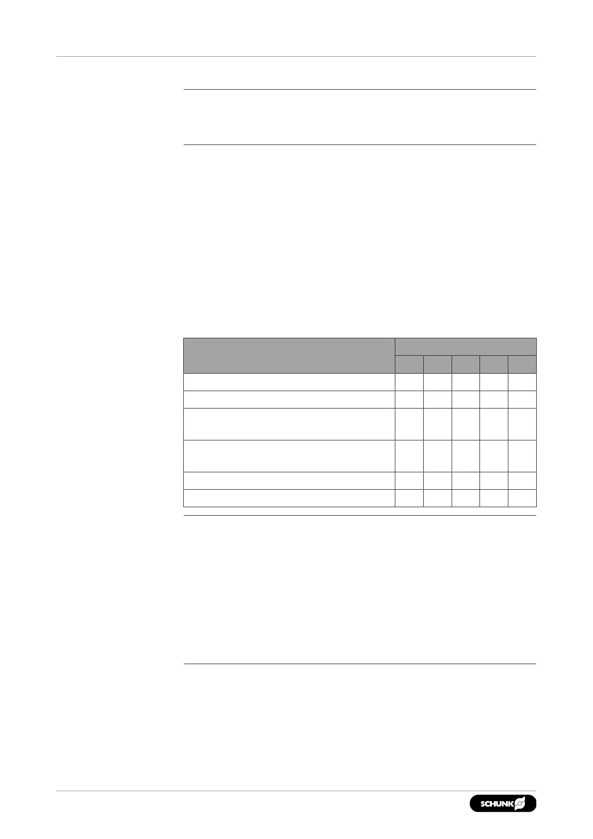
5.5.1 Overview of sensors
Designation PGL-plus-P
10 13 16 20 25
Inductive proximity switch IN 80 X X X X X
Magnetic switch MMS 22 X X X X X
Programmable magnetic switch
MMS 22-PI2
X X X X X
Programmable magnetic switch
MMS 22-PI1
X X X X X
Magnetic switch MMS 22-IOL X X X X X
Analog magnetic switch MMS 22-A X X X X X
Variant IOL
NOTE
• The variant with integrated sensor system (IOL) has a sensor
integrated in the gripper. The positions can be monitored over
the entire stroke via the IO-Link interface. This variant does not
require assembly.
• The positions "Gripper closed" and "Gripper open" are set in
the factory.
• For more information on commissioning, see Software Manual
"PGL-plus-P with Integrated Sensor System, IO-Link Protocol".