Assembly and settings
34 02.00 | PGL-plus-P | Assembly- and Operating Manual | en | 1508050
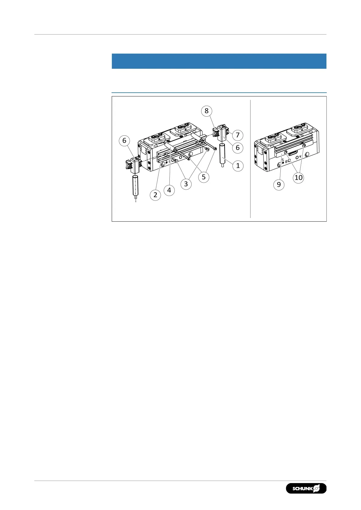
5.5.4 Mounting inductive proximity switch IN
NOTICE
Risk of damage to the sensor during assembly!
• Observe the maximal tightening torque.
To mount the IN proximity switches, the product must be
retrofitted with a special attachment kit. This attachment kit is
available from SCHUNK. See catalog for types that can be ordered.
Alternatively, the product can be ordered with pre-assembled
attachment kit.
Mounting the attachment kit
1. Size10–13: If the attachment kit is mounted on the front,
loosen screws(10) and remove the sensor holder for the
magnetic switch(9).
2. Secure the sensor rail(2) with screws(3).
✓ Size16–25: Measure the distance between the top edge of
the sensor rail and the housing. The following distance
should be available:
Size16: 1.2mm,
Size20:0.4 mm,
Size25:0.8 mm
If the distance is too large, turn the sensor rail by 180° and
secure.
3. Secure the control cam(4) with screws(5).
4. Loosen screw(8) and push sensor holder(6) into the side of
the sensor rail(2). Observe the installation position, the long
side must point downwards.