Assembly and settings
5.3.3 Electrical connection - IOL variant
NOTICE
Risk of damage to the electronics!
A faulty connection can cause damage to the internal electronics.
• The supply network must be a "PELV" network type for power
and logic.
• Observe the PIN assignment of the connecting terminals.
• Maximum cable length: 20m.
• Make sure that all components are properly grounded.
NOTE
Note on EMC conformity (in accordance with EN 61000-6-4:2007
+ A1:2011):
• The product may only be used in DC distribution networks with
an expansion of < 30 m.
Components of the electrical connection
Plug connector
product
Plug connector
provided by the customer
Connector 4-pin, M8, A-coded Connection cable 4-pin, M8
socket, A-coded
Voltage supply and
control
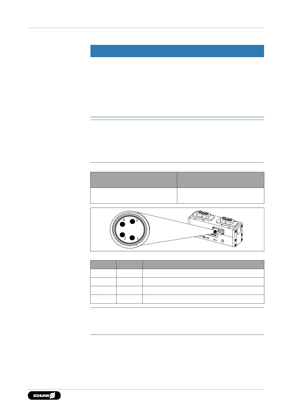
IO-Link connector, 4-pin, M8
Pin Signal Description
1 L+ +24V
2 I/Q Switching signal DI (SIO)
3 L- GND
4 C/Q Switching signal DI (SIO) or IO-Link (SDCI)
NOTE
For more information, see Software Manual "PGL-plus-P with
Integrated Sensor System, IO-Link Protocol".
2702.00 | PGL-plus-P | Assembly- and Operating Manual | en | 1508050