Page 156
STAT
IM
2000/2000S Service Guide
96-106775 Rev 5.0
7. Electrical and Electronic Components
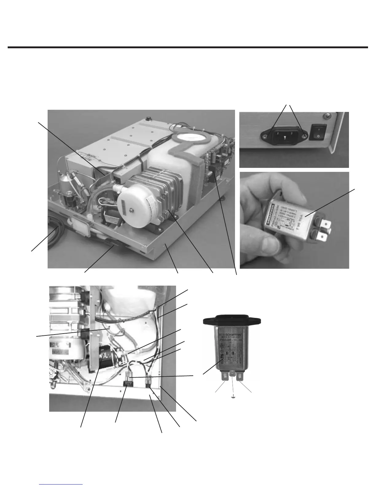
Power (on/off) Switch
Removing the Power Switch
To remove the power switch (2), proceed as follows, (See Figure 21):
STATIM 5000/5000S/5000 G4 Service Guide
Position N
Position P
1. detachable line cord
(not shown)
2. power switch
3. A.C. inlet receptacle
4. line filter
5. four screws (obscured)
6. compressor assembly
7. chassis
8. thermocouple leads
9. white wire
10. black wire
11. pump
12. white wire (J1-1)
13. Controller Board
14. black wire (J1-2)
15. power switch tabs
16. green wire
17. ground post
18. two screws
19. A.C. inlet receptacle tabs
Figure 21
4
2
1
17
3
4
7 6
13
8
7
19
9
11
15
10
16
18
14
12