


T
Tom WilcoxSep 22, 2025
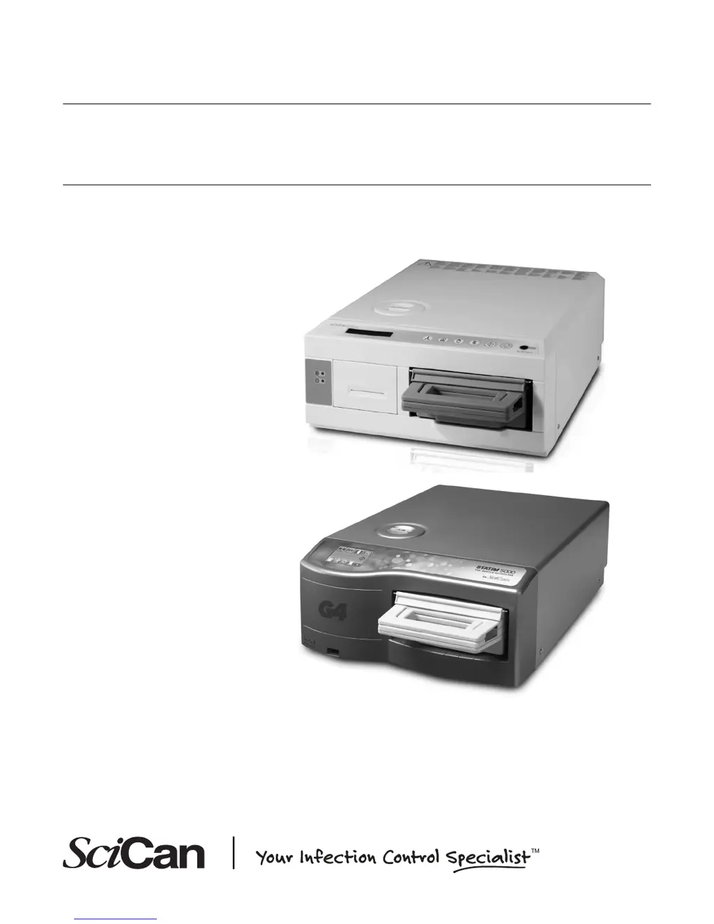
What to do when SciCan Statim 5000 Laboratory Equipment says 'MSD/FLASH FULL'?
- AAdriana PerezSep 22, 2025
If the SciCan Laboratory Equipment displays the message 'MSD/FLASH FULL REPLACE MSD', export the data from the device.


