Page 243
STAT
IM
2000/2000S Service Guide
96-106775 Rev 5.0
12. Printer and Data Logger
STATIM 5000/5000S/5000 G4 Service Guide
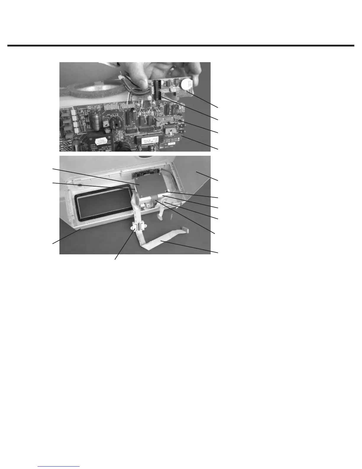
To replace the Printer Interface Board, proceed as follows (see Figure 1):
1. Connect the Printer Interface ribbon cable (10) to Printer Interface Board header P1. Cable
(assemblies may differ). If the connector is not polarized, note the orientation of Pin 1 of the
connector and Pin 1 of the board.
2. Connect the Printer ribbon cable (9) connector to Printer Interface Board header P2.
3. Place the Printer Interface Board, component side down, on the module. Replace the Printer
Interface Board shield (8) and insert the four screws (7) retained during disassembly.
4. If the Printer Interface Board has been repaired, or is a new Printer Interface Board, the print
quality may require adjustment. See; “Adjusting Print Quality” and “Printer Interface Board:
Important Notes.”
Printer Interface Board – Important Notes
1. In order to operate with version 1.1 STATim Controller Boards, Printer Interface Boards version
2.0 and higher require the removal of jumper J2.
2. Nylon spacers are required for mounting version 1.1 Printer Interface Boards ONLY.
1. Printer module assembly
2. Cover
3. Screws
4. Fascia assembly
5. Controller Board
6. Printer Interface Board
7. #1 Phillips screws
8. Printer Interface Board shield
9. Printer ribbon cable
10. Printer Controller ribbon cable
11. Ferrite core
12. Controller Board P2 connector
13. Pressure Interface Board
14. Pressure Interface Board P2
connector
Figure 1
13
14
12
5
2
8
6
4
11
9
7
1
3
10