Page 168
STAT
IM
2000/2000S Service Guide
96-106775 Rev 5.0
8. Water Pumps, Reservoir, and Compressor
Performing inline filter maintenance
For maintenance of units with in-line filters, proceed as follows
(See Figures 6 and 10):
This filter should be replaced every 2000 cycles or every two years.
1. Drain the reservoir (1). See, Tools, Maintenance Schedules,
Procedures and Testing.
2. Remove the four screws with washers (2) securing the compressor
/ bracket assembly (3). See, Compressor.
3. If the pressure transducer (4) is present disconnect the transducer
connector (5). See PressureTransducer.
4. Remove the compression nut (6) holding the compressor output
tube (7) to the compressor and disconnect the tube.
5. Rest the compressor / bracket assembly to one side to access the pump.
6. Cut and remove the cable ties (8) connecting the filter and inlet/outlet tubes.
7. Remove the filter (20) from the tubes.
Note: the filter is directional, so check the orientation of the filter before removing.
8. Insert the new filter in to the inlet and outlet tubes. Check the flow orientation of the filter.
9. Secure the tubes to the filter with new cable ties.
10. Run a sterilization cycle and observe filter and tubes for leaks. Check LCD read-outs for
messages indicating cycle status.
11. The in-line filter kit can be retro-fitted and is available as part # 01-106637S and includes the
filter, all necessary tubing and installation instructions.
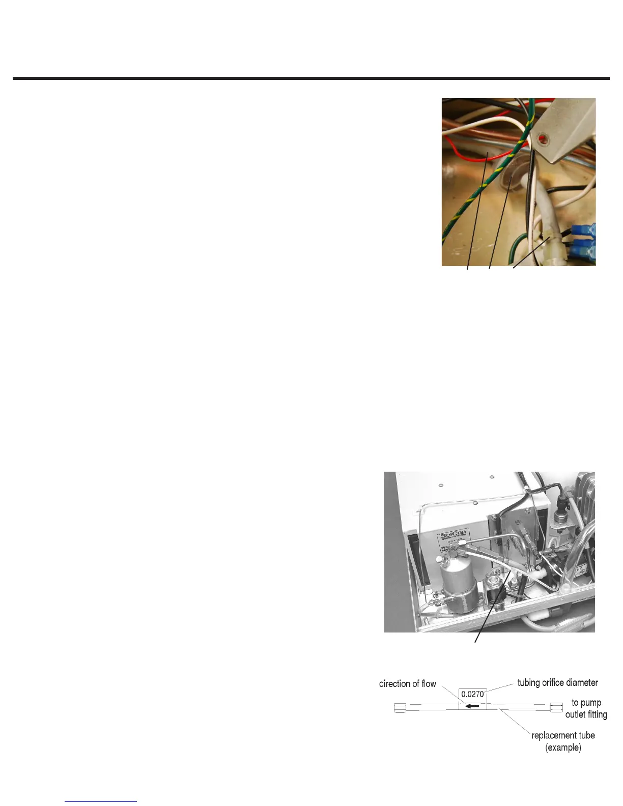
Performing Pump Tube Replacement
The pump tube located between the pump and the
steam generator is designed to control the flow of water
into the steam generator so that it receives the precise
amount of water required at specific points in the
sterilization cycle. The tube is directional (pump to steam
generator) and contains a precision orifice tube inside
the main tube that has a precise diameter that controls
the volume passing through into the steam generator.
The orifice tube is located at the steam generator end
of the main pump tube. The diameter of the fitting
is represented on the outside of each pump tube by
a numeric value. The larger the value, the larger the
diameter of the orifice.
If the filters are clean and the pump flow parameters
are not correct, then it may be possible to recover
the correct water delivery by the replacement of the
pump tube with one of larger or smaller diameter as
appropriate.
Figure 10
Figure 11
9 20 8
Pump tube
8. Cable tie
9. Inlet tube
20. In-line filter
STATIM 5000/5000S/5000 G4 Service Guide