Page 226
STAT
IM
2000/2000S Service Guide
96-106775 Rev 5.0
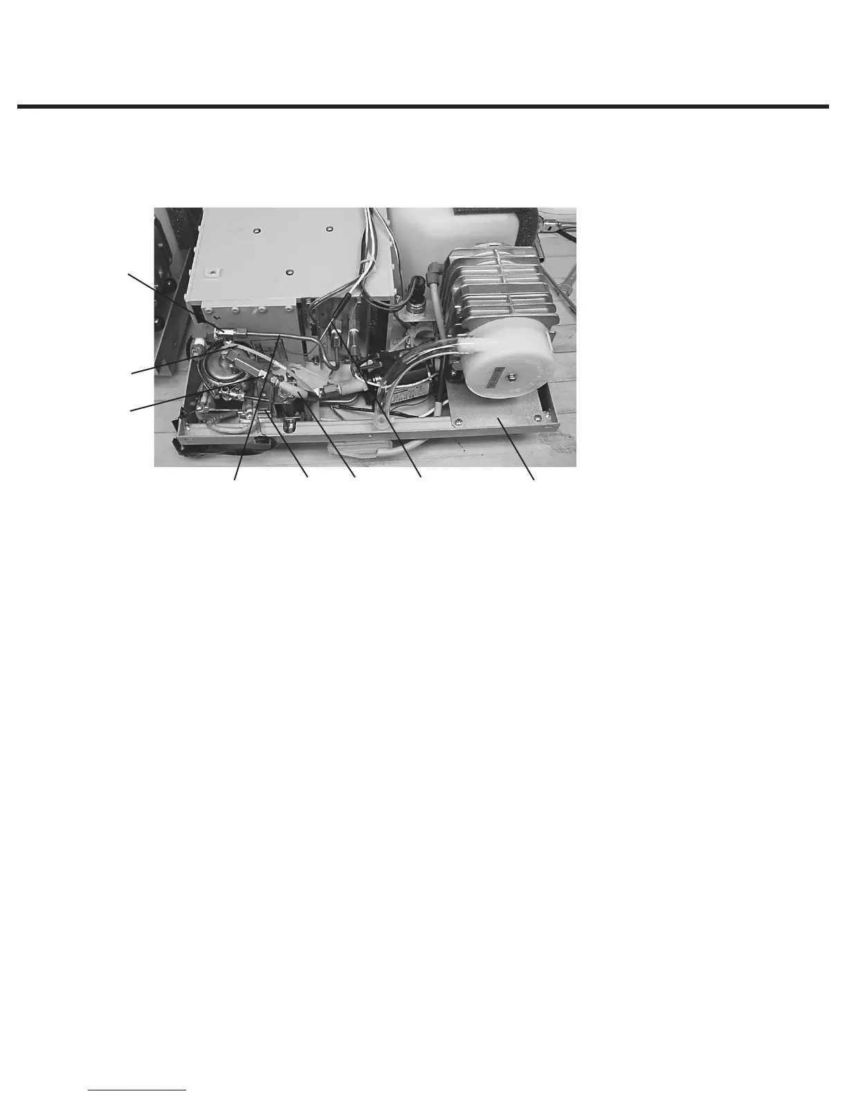
11. Steam Generator, Check Valve, Thermal Fuse and Pressure Relief Valve
Removing the Stainless Steel Steam Generator
To remove the steam generator, proceed as follows (see Figure 3):
1. Turn the power switch OFF, and unplug the unit. Remove cover.
2. Referring to the PCB inset graphic in Figure 3 above, remove the pressure interface board or
printer cable (if fitted) from the blue socket and disconnect the steam generator thermocouple
wires (1) from the controller board (2) terminal positions BOILER +Y and -R and disconnect the
ground lead terminal (3) from the position marked BOILER directly above the terminals. Leave
the screws with contact washers in the terminals.
3. Disconnect the electrical connections of both steam generator power cables at the PC
board. Look for the connections on the left side of the board marked “BL”. Disconnect wire
N and wire L of the “BL” set. Disconnect the black thermal fuse (4) wire from controller board
connector terminal block J1-3.
4. Trace the path of the wires to the steam generator and cut the cable ties holding them in
place. Separate the wires from the wiring harness.
Refer back to Figure 4 for the remainder of the procedure.
5. Carefully cut the cable ties securing the steam generator thermocouple lead (7) and other
wires to the armature.
6. Carefully cut the cable tie holding the compressor tube (5) onto the check valve inlet and pull
the tube off the valve.
7. Disconnect the compression nut (1) holding the Teflon™ tube (4) from the top of the steam
generator.
8. Using a 7/16 wrench on the compression nut (1) connected to the steam generator outlet tube
and a 3/8 wrench on the T-fitting (3), disconnect steam generator outlet tube (2). When the nut
is unscrewed completely, pull the tube gently away from the T-fitting to disengage it from the
fitting.
9. Loosen the mounting screws that hold the steam generator bracket to the chassis and, using
the bracket’s key slot, slide the steam generator out of position and remove.
Figure 3
78 5
1
4
3
STATIM 5000/5000S/5000 G4 Service Guide
1. Compression nut
2. Steam generator
outlet tube
3. T-fitting
4. Teflon
™
tube
5. Compressor tube
6. Compressor bracket
7. Steam generator
thermocouple lead
8. Bracket adaptor
2 6