Page 191
STAT
IM
2000/2000S Service Guide
96-106775 Rev 5.0
8. Water Pumps, Reservoir, and Compressor
STATIM 5000/5000S/5000 G4 Service Guide
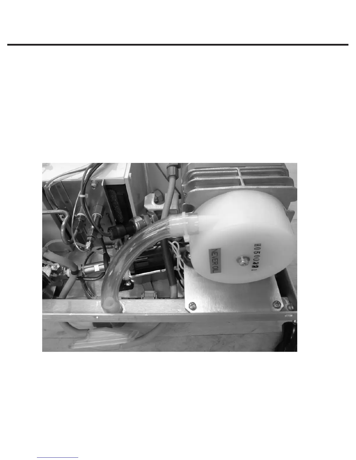
4. Install the compressor with its bracket onto the chassis using the screws provided. On the
machine-front side of the bracket, only 2 of the 3 screw holes need to be used.
5. For 5000S units, reinstall the transducer onto slot on the compressor bracket by tightening the
nut against the bracket.
6. Connect the compressor wires to the PCB, wire 9 (colored brown or black) to terminal L and
wire 10 (colored blue or white) to terminal N. Use 3 cable ties to harness all the wires, ensure
that the wires are tucked inside the chassis underneath the foam strip on the reservoir. Connect
the ground wire to the ground post on the chassis.
7. Feed silicone tubing through grommet on chassis and attach to biological filter.
8. Attach PVC tubing (74-101305) to the compressor. Apply cable tie (53-100231A). Rotate the
head of cable tie so that it is facing down. Attach other end of the tubing to air pre-filter fitting
on chassis and apply cable tie.
9. Rotate cable tie head away from chassis back wall.
10. Reinstall the cover.
11. A dielectric strength test (Hi-Pot) AND a protective bonding impedance test (ground continuity)
must be performed on the STATIM when the work is completed and after the cover has been
returned to the unit.
Figure 31