Section 12 HULL/BODY
Subsection 02 (ADJUSTMENT AND REPAIR)
SMR2000-071_12_02A.FM 12-02-11
STORAGE COMPARTMENT
INNER SHELL
To remove inner shell, proceed as follows:
CAUTION: Failure to follow this order may lead
to damaging inner plastic studs.
Remove retaining screws.
Gently pull on large end (rear end) and pull apart
towards the small end (front). See illustration.
1. Gently pull starting this end
2. Finish with this end
For installation, proceed as follows:
• Sand both inner and outer shells in area to be
glued.
• Clean to remove any dust with isopropylic alco-
hol. Let dry.
• Apply a 2 mm (3/32 in) bead of Loctite 454.
• Reinstall inner shell with its retaining screws.
• Tighten screws starting with the one at the
small end (front) and finish with rear end. Care-
fully hand tighten.
STORAGE COMPARTMENT
COVER ADJUSTMENT
Adjust lock pin no. 3 as per following specifica-
tions:
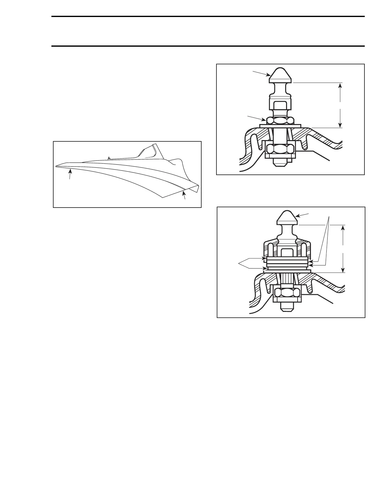
RX AND SOME GTX DI MODELS
1. Lock pin (apply Loctite 271)
2. Adjustment nut
A. 34 ± 1 mm (1-11/32 ± 3/64 in)
SOME GTX DI MODELS
1. Lock pin (apply Loctite 243)
2. Rubber washer
3. Flat washers
A. 39.2 ± 1 mm (1-35/64 ± 3/64 in)
NOTE: Some GTX DI models have a floating type
lock pin. It is normal to have a front and aft play of
the lock pin. To adjust, tighten lock pin until any
vertical play is eliminated. Make sure a front and
aft play remains when pressing by hands.
1
F16L05A
2
F06L04A
A
2
1
F07L09A
A
3
12
 Loading...


