Section 14 WIRING DIAGRAMS
Subsection 01 (WIRING DIAGRAMS)
SMR2000-073_14_01A.FM 14-01-1
WIRING DIAGRAMS 0
WIRE COLOR CODES
First color of a wire is the main color. Second color
is the tracer.
Example: YELLOW/BLACK (YL-BK) is a YELLOW
wire with a BLACK tracer.
WIRE DIGIT CODES
First number indicates in which connector the
wire is plugged in.
Second number indicates the position of the wire
in the connector.
The letter at the end of the number (if applicable)
indicates a common circuit in the MPEM printed
circuit with another wire bearing the same letter.
Example: 2-18 (g).
The first number indicates that the wire is posi-
tioned in the connector no. 2 of the MPEM.
The second number indicates that the wire is po-
sitioned in the terminal no. 18.
The letter (g) indicates a common circuit with an-
other wire(s) bearing the same letter (g) in the cir-
cuit.
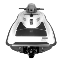
DEUTSCH CONNECTORS
Deutsch connectors are used to connect wiring
harness to magneto, to electrical box (some mod-
els) and to diagnostic tool (VCK) on DI models.
1. Male housing
2. Female housing
3. Secondary lock
4. Sealing cap
CAUTION: Do not apply dielectric grease on con-
tacts inside plug connector.
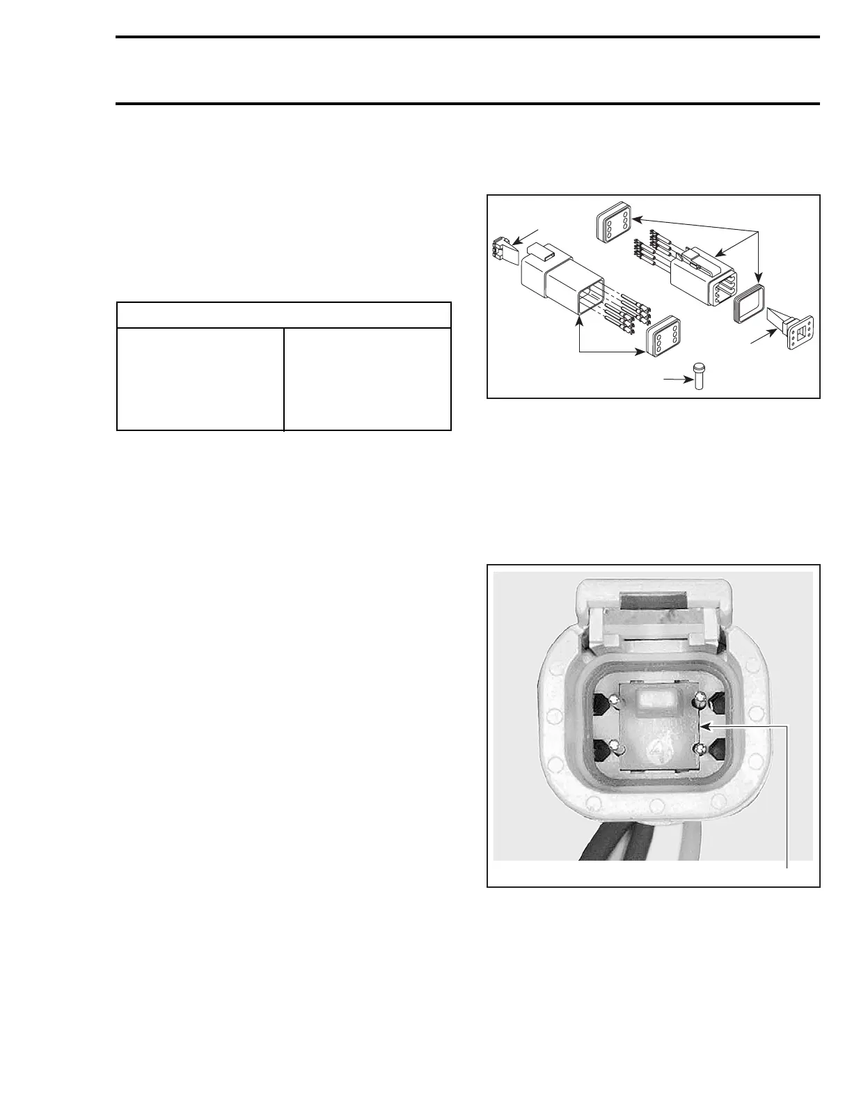
To remove wire contacts from housing, proceed
as follows:
– Using a long nose pliers, pull out the lock.
FEMALE HOUSING
1. Female lock
COLOR CODE
WH — WHITE
RE — RED
PU — PURPLE
GR — GREEN
GY — GREY
PK — PINK
BK — BLACK
YL — YELLOW
TA — TAN
BW — BROWN
BL — BLUE
OR — ORANGE
F00H1CA
1
3
4
2
3
1
V01G0OA