Section 05 ENGINE MANAGEMENT (DI)
Subsection 03 (COMPONENT INSPECTION AND ADJUSTMENT)
SMR2000-051-05-03A.FM 05-03-21
NOTE: Reset must be done each time the throttle
position sensor (TPS) is loosened or removed or
throttle body(ies) is(are) replaced or MPEM is re-
placed.
CAUTION: An improperly adjusted TPS may
lead to poor engine performance and emission
compliance could possibly be affected.
Use the vehicle communication kit (VCK) with the
B.U.D.S. software to perform this adjustment.
Ensure the throttle body plate stop lever rest
against its stopper. Open throttle approximately
one quarter then quickly release. Repeat 2 - 3 times
to settle throttle plate. If stopper does not rest
against its stop lever, perform throttle cable ad-
justment. Refer to Throttle Body in Air Induction
System above.
Push the Reset button in the Setting section of
B.U.D.S.
NOTE: There is no idle speed adjustment to per-
form. The MPEM takes care of that. If TPS are not
within the allowed range while resetting the
closed TPS, the MPEM will generate a fault code
and not accept the setting.
Start engine and make sure it operates normally
through its full engine RPM range. If fault codes
appear, refer to DI System Fault Codes in DIAG-
NOSTIC PROCEDURES section for more informa-
tion.
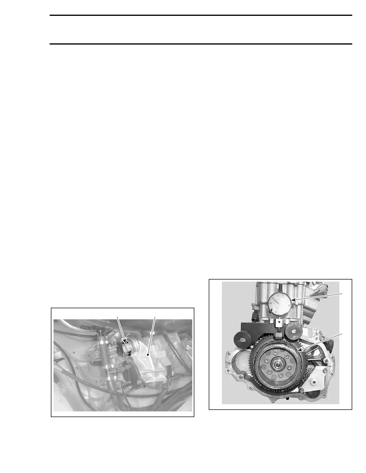
CRANKSHAFT POSITION
SENSOR (CPS)
1. Magneto cover
2. CPS connector
Check for RPM display at the information center
while cranking engine. If it displays approximate-
ly 300 RPM, the CPS circuitry is properly working.
Otherwise, validate the information center is
working by activating the tachometer using the
software B.U.D.S. under Activation. If it does not
display 3000 RPM, the information center may be
faulty and needs to be tested.
If the information center correctly displayed 3000
RPM, perform the following tests.
NOTE: Take into account that a CPS fault can be
triggered by bent or missing encoder wheel teeth.
Check the teeth condition. Also, bad connections
in magneto connector could generate electrical
noise that would make you wrongly think the CPS
is faulty. Check pins and wires.
Encoder Wheel Inspection
To check the encoder wheel for bent teeth, pro-
ceed as follows.
Remove magneto cover. Refer to magneto sys-
tem in ENGINE section.
Install a dial indicator on cranckase casting. Posi-
tion the gauge on a tooth and set it to zero (0).
Rotate flywheel and check needle movement. The
maximum allowed difference between teeth is
0.15 mm (.006 in). Otherwise, straighten the tooth
or replace the encoder wheel.
1. Encoder wheel
2. Dial indicator
Properly reinstall cover.
2
F12R0OA
1
1
F12R14A
2