Section 04 ENGINE
Subsection 04 (MAGNETO SYSTEM)
04-04-4 SMR2000-045_04_04A.FM
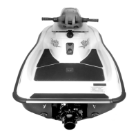
TYPICAL
1. Puller
Tighten puller screw and at the same time, tap on
screw head using a hammer to release engine fly-
wheel from its taper.
CAUTION: Be careful after flywheel removal
not to bend the encoder wheel teeth. Also pay
attention when putting away. If you suspect a
bent tooth, refer to ENGINE MANAGEMENT for
inspection procedure.
Stator and Trigger Coil/CPS
(Crankshaft Position Sensor)
Loosen screws no. 20 and no. 21 to remove the
stator no. 9 and trigger coil/CPS no. 10 from the
engine magneto cover.
1. Remove screws
CLEANING
Clean all metal components in a solvent.
CAUTION: Clean coils and magnets using only
a clean cloth.
Clean crankshaft taper and threads using acetone.
Apply the acetone on a rag first then clean the
crankshaft.
ASSEMBLY
Stator and Trigger Coil/CPS
(Crankshaft Position Sensor)
Install the stator no. 9 and trigger coil/CPS no. 10
in engine magneto cover. Torque screws to 9 N•m
(80 lbf•in).
Reinstall wiring harness bracket no. 29 using tap-
tite screws no. 30.
Torque trigger coil/CPS screws no. 21 to 9 N•m
(80 lbf•in).
Torque stator screws no. 20 to 13 N•m (115 lbf•in).
NOTE: The trigger coil/CPS is not adjustable.
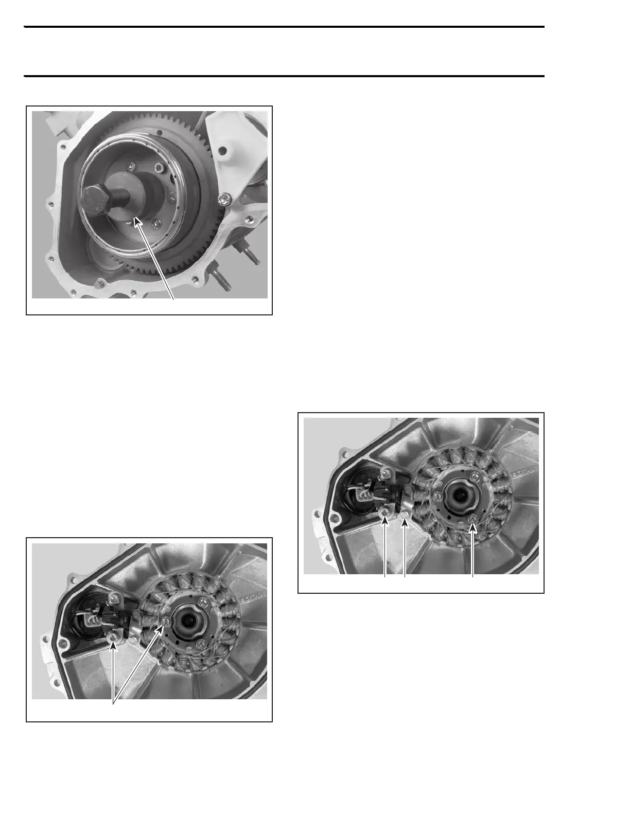
TYPICAL
1. Torque to 9 N•m (80 lbf•in)
2. Taptite screws
3. Torque to 13 N•m (115 lbf•in)
F06D0NB
1 2 3