Section 06 COOLING SYSTEM
Subsection 02 (CIRCUIT, COMPONENTS AND CARE)
SMR2000-054_06_02A.FM 06-02-9
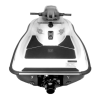
Remove the tapered needle from valve housing.
1. Remove tapered needle
Pull the valve slightly. Using pliers, release the
clamp which retains the bellows.
Remove valve and bellows.
Loosen clamp to separate valve from bellows.
1. Clamp
Inspection
Inspect parts for damage. Verify especially bel-
lows for cracks.
Assembly
Assembly is essentially the reverse of disassem-
bly procedures.
CARE
For flushing purposes, the cooling system is
equipped with either a fitting spigot or a hose
adapter depending upon the model.
For flushing operation, a coupler hose is available
(unnecessary for models with the hose adapter) to
connect to the fitting spigot. A garden hose is
used to flush the whole system by backwash. For
flushing procedure, refer to FLUSHING AND LU-
BRICATION.
For winterization of cooling system, refer to STOR-
AGE.
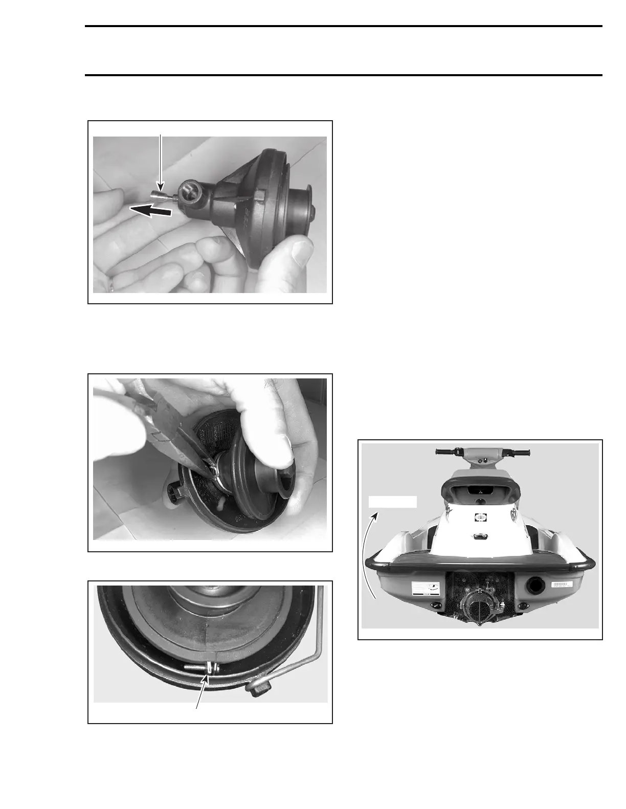
When servicing the hull, always rotate watercraft
clockwise (seen from the rear). Rotating water-
craft on the opposite side could allow residual wa-
ter in tuned pipe to enter the engine and cause
damage.
TYPICAL
F01E20A
1
F01E21A
F01E24A
1
Max. 90°
F06L11B