Section 10 PROPULSION SYSTEM
Subsection 03 (DRIVE SYSTEM)
10-03-4 SMR2000-066_10_03A.FM
Boot
Loosen gear clamp no. 11 holding boot, then care-
fully pull boot and carbon ring no. 8 from hull in-
sert.
Carbon Ring
Loosen gear clamp no. 9 then pull carbon ring from
boot no. 10.
INSPECTION
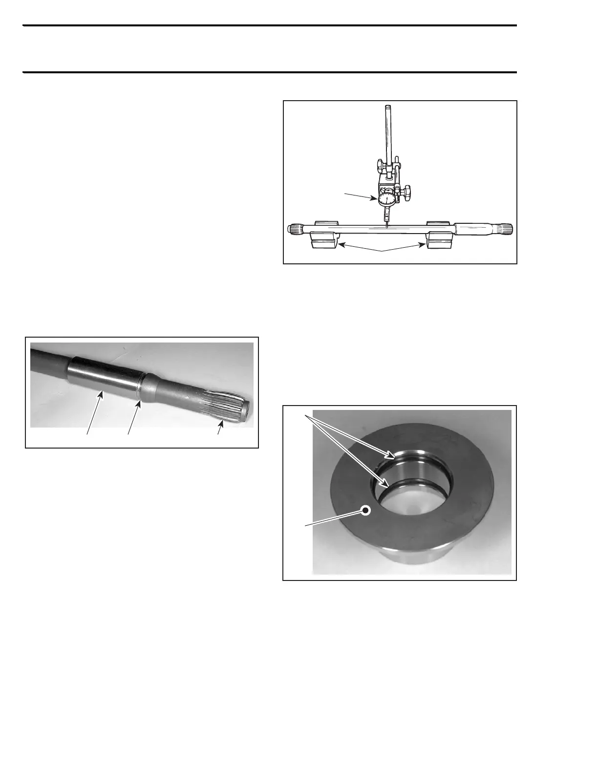
Drive Shaft
Inspect condition of drive shaft and PTO flywheel
splines.
Inspect condition of groove.
With your finger nail, feel machined surface of
drive shaft. If any irregular surface is found, renew
drive shaft.
1. Surface condition
2. Groove condition
3. Splines condition
Excessive deflection could cause vibration and
damage to drive shaft splines, impeller, flywheel
or floating ring (seal carrier depending upon the
model).
Place drive shaft on V-blocks and set-up a dial gauge
in center of shaft. Slowly rotate shaft; difference
between highest and lowest dial gauge reading is
deflection. Refer to the following illustration.
Maximum permissible deflection is 0.5 mm (.020 in).
MEASURING DRIVE SHAFT DEFLECTION
1. Dial gauge
2. V-blocks
Damper
Visually inspect shape of dampers no. 13 for de-
formation or other damage.
Floating Ring and O-Ring
Inspect condition of O-rings no. 7 and floating ring
contact surface.
1. O-rings
2. Floating ring contact surface
1
2
F01J15A
F01I0GA
1
2