30
Operating Instructions – MOVIFIT® basic
5
Connections of MOVIFIT
®
basic with AS-Interface
Electrical installation
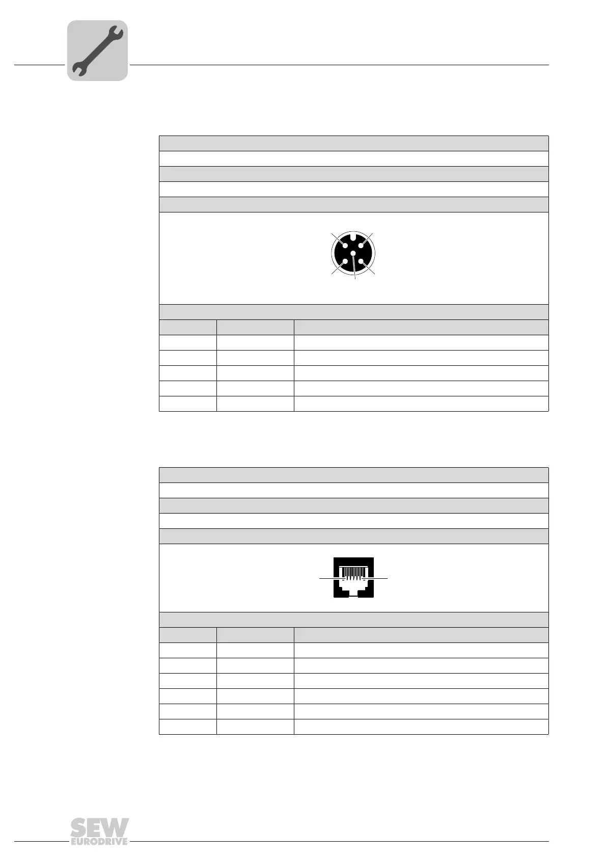
5.6.3 X23: Binary input sensor 3
The following table provides information about this connection:
5.6.4 X50: Diagnostic interface
The following table provides information about this connection:
Function
Binary input sensor 3
Connection type
M12, 5-pole, female, A-coded
Wiring diagram
2264816267
Assignment
No. Name Function
1 +24 V DC 24 V output (sensor supply)
2 n. c. Not connected
3 0V24 0V24 reference potential
4 DI3 Binary input sensor 3
5 PE Equipotential bonding/protective earth conductor
1
4
3
2
5
Function
Diagnostics and programming interface
Connection type
RJ11 (6P6C)
Wiring diagram
3163123211
Assignment
No. Name Function
1 n. c. Not connected
2 RS+ RS-485 data cable (+)
3RS − RS-485 data cable (–)
4 +24 V DC 24 V output for keypad
5 0V24 0V24 reference potential for keypad
6 n. c. Not connected