34
Operating Instructions – MOVIFIT® basic
5
PC connection
Electrical installation
5.9 PC connection
The MOVIFIT
®
basic inverter is equipped with an X50 diagnostics interface (RJ-11
socket) for startup, parameterization and service.
The diagnostics interface is located in the connection block of the control unit.
You must remove the screw plug before plugging in the connector into the diagnostic
interface.
WARNING Danger of burns due to hot surfaces of the MOVIFIT
®
basic unit.
Severe injuries.
• Wait for the MOVIFIT
®
basic unit to cool down sufficiently before touching it.
NOTICE Loss of the ensured degree of protection if the screw plug of the diagnostic in-
terface X50 is not installed.
Damage to the MOVIFIT
®
basic unit.
• If no screw plug is covering the diagnostic interface, you have to make sure that no
moisture can ingress into the MOVIFIT
®
basic unit.
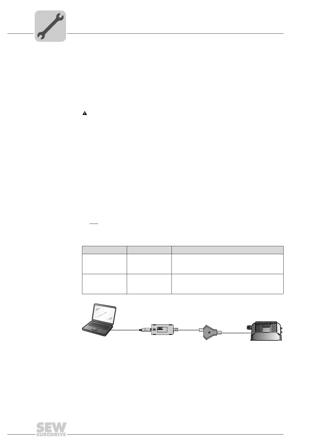
The diagnostic interface can be connected to a conventional PC/laptop with the follow-
ing accessories:
• USB11A interface adapter
•and
OP LT 003 C adapter
Scope of delivery:
Type Part number Scope of delivery
USB11A 0 824 831 1 – USB11A interface adapter
– USB cable
– Cable with RJ10 – RJ10 plug connectors
OP LT 003 C 1 824 368 1 – OP LT 003 C adapter
with DC 24 V -> DC 5 V voltage converter
– Cable with RJ45 – RJ11 plug connectors
9007202071149707
MOVIFIT basic
PC +
MOVITOOLS
USB
®
®
RJ10
RJ45
RJ11
USB11A
OP LT 003 C