Operating Instructions – MOVIFIT® basic
65
8
Status and error display
Service
8.2 Status and error display
8.2.1 Meaning of the status LED
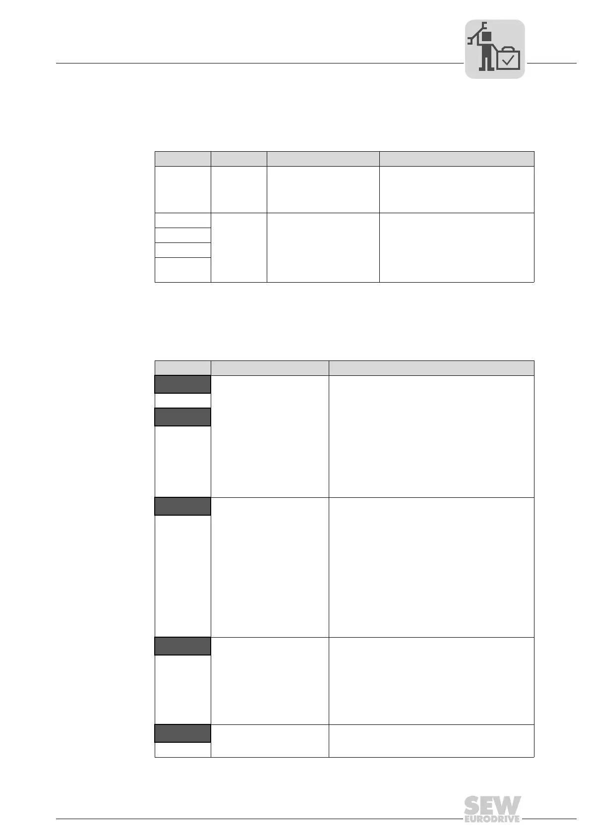
The following table shows the meaning of the status LED in case of a fault:
8.2.2 Fault list for MOVIFIT
®
basic
The LT-BG operator terminal displays the faults that occurred at the MOVIFIT
®
basic
drive. In addition, you can read out the 4 latest faults from parameter P1-13 error log on
the PC.
LED color LED status Meaning Solution
Red On A fault has occurred
Read out fault code with LT-BG or LT
Shell software.
Remedy fault as described in chapter
"Fault list for MOVIFIT
®
basic".
Red
Flashing Internal unit error Contact SEW Service.
Red/yellow
Green/red
Green/yel-
low
Error code Fault Solution
O-I
Overcurrent at inverter out-
put to the motor.
Motor overload.
Overtemperature at the
heat sink of the inverter.
• Check motor and connection cables for phase
short circuits or ground faults.
• Check load for blocking, stalling, or shock
loads.
• Make sure that the parameters P1-07, P1-08,
and P1-09 are set correctly according to the
motor nameplate.
• For vector control (P4-01 = "0" or "1"): Check
the motor power factor in P4-05.
• Make sure that the auto-tune process for the
connected motor has been completed suc-
cessfully.
• Increase the ramp time in P1-03.
hO-I
I_ t-trP
An inverter overload error
occurs when the inverter
has delivered > 100% of the
nominal current for a certain
time (defined in P1-08). The
display is flashing to indi-
cate the overload.
• Increase the acceleration ramp or reduce the
motor load.
• Make sure that the cable length meets the
requirements.
• Make sure that the parameters P1-07, P1-08,
and P1-09 are set correctly according to the
motor nameplate.
• In vector control mode (P4-01 = "0" or "1"),
check the motor power factor in P4-05.
• Make sure that the auto-tune process for the
connected motor has been completed suc-
cessfully.
• Check the load mechanically. Make sure that
the load can move freely and that there are no
blockages or other mechanical faults.
PS-trP
Internal output stage error Error when enabling the drive:
• Check for incorrect wiring or short circuit.
• Check for phase short circuits or ground faults.
Error during operation:
• Check for sudden overload or overtempera-
ture.
• Provide additional space or cooling, if neces-
sary.
O_Uo lt
DC link overvoltage • Check whether the supply voltage is too high.
• If the inverter switches off during deceleration,
increase the deceleration ramp in P1-04.