Operating Instructions – MOVIFIT® basic
31
5
Connections of MOVIFIT
®
basic with binary control
Electrical installation
5.7 Connections of MOVIFIT
®
basic with binary control
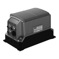
5.7.1 X11: Signal inputs 0 and 1 of MOVIFIT
®
basic
The following table provides information about this connection:
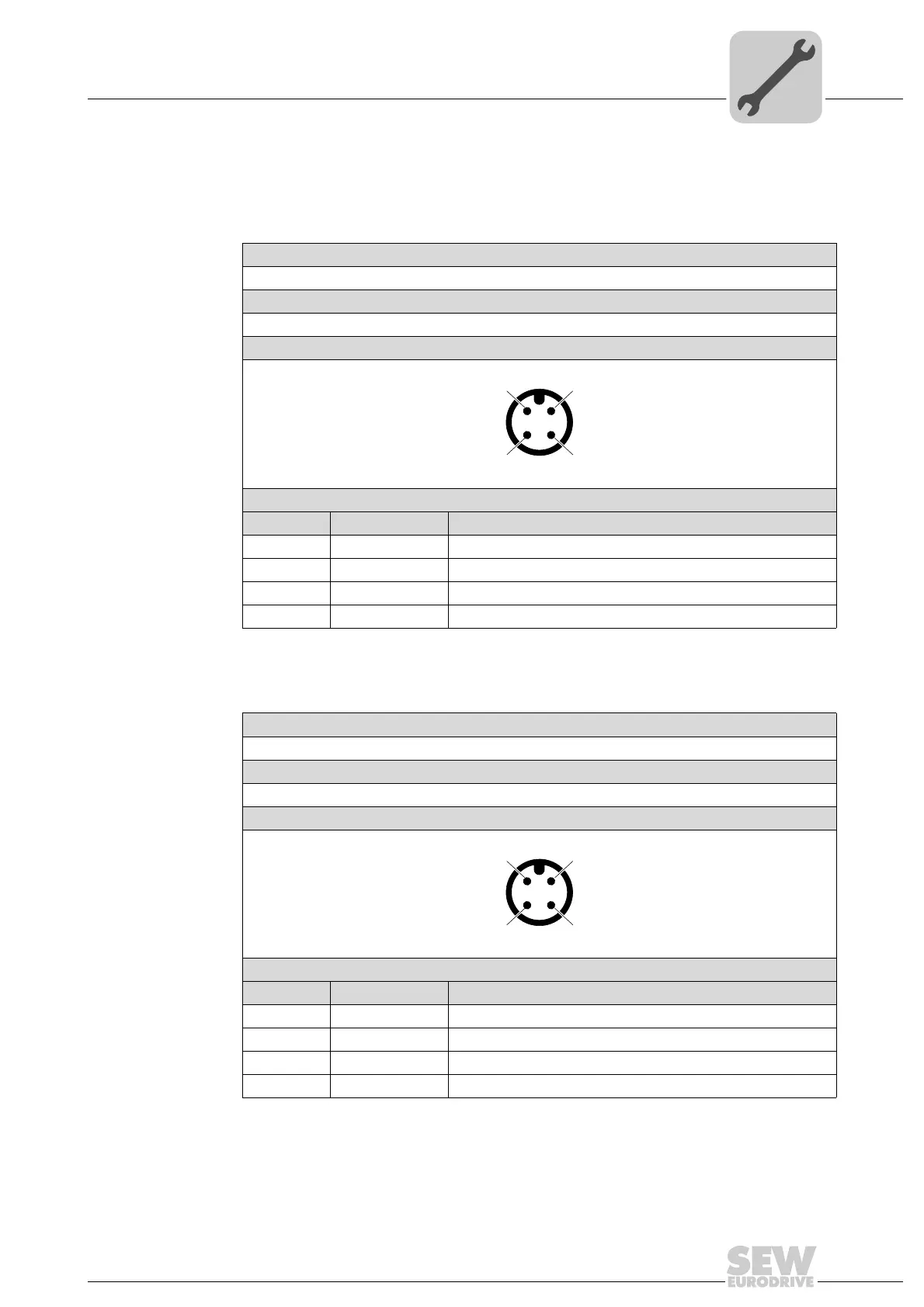
5.7.2 X12: Signal inputs 2 and 3 of MOVIFIT
®
basic
The following table provides information about this connection:
Function
Binary inputs 0 and 1
Connection type
M12, 4-pole, male, A-coded
Wiring diagram
2718233355
Assignment
No. Name Function
1 n. c. Not connected
2 DI1 Binary input 1
3 0V24 0V24 reference potential
4 DI0 Binary input 0
Function
Binary inputs 2 and 3
Connection type
M12, 4-pole, male, A-coded
Wiring diagram
2718233355
Assignment
No. Name Function
1 n. c. Not connected
2 DI3 Binary input 3
3 0V24 0V24 reference potential
4 DI2 Binary input 2