Operating Instructions – MOVIFIT® basic
55
7
Operating displays of MOVIFIT
®
basic (LEDs)
Operation
7 Operation
7.1 Operating displays of MOVIFIT
®
basic (LEDs)
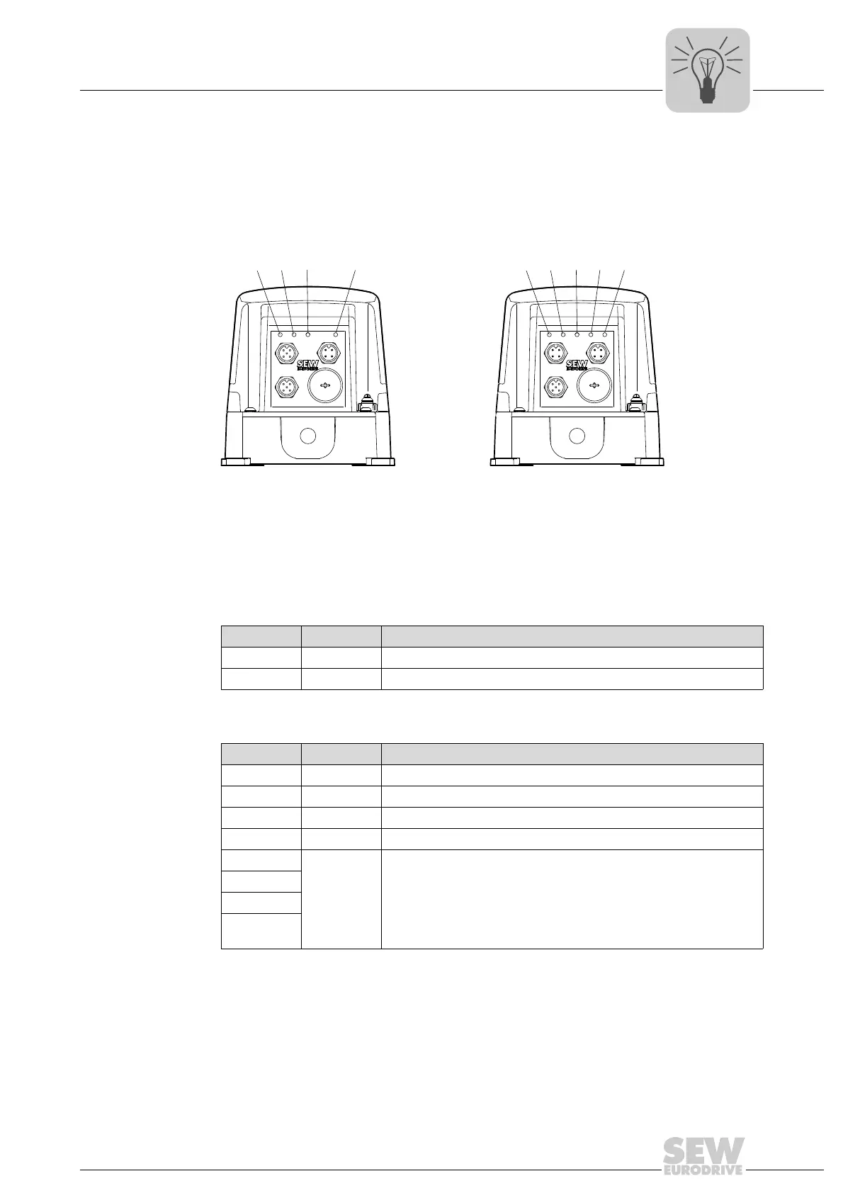
The following figure shows the LEDs of MOVIFIT
®
basic:
7.1.1 LEDs "DI0 – DI3"
7.1.2 LED "Status"
MOVIFIT
®
basic with AS-Interface MOVIFIT
®
basic with binary control
2816401035 2816399115
[1] LED "DI3" [5] LED "DI3"
[2] LED "DI2" [6] LED "DI2"
[3] LED "Status" [7] LED "Status"
[4] LED "AS-Interface" [8] LED "DI1"
[9] LED "DI0"
DI3 DI2
AS-Interface
STATUS
[1] [2] [3] [4]
DI3 DI2 DI1 DI0
STATUS
[5] [6] [7] [8] [9]
LED color LED status Meaning
– Off Input signal at binary input DI. open or "0"
Yellow Illuminated Input signal present at binary input DI.
LED color LED status Meaning
– Off No voltage supply
Green On MOVIFIT
®
basic drive is enabled
Yellow On MOVIFIT
®
basic drive is ready for operation
Red On An error has occurred
Red
Flashing Internal unit error
Red/yellow
Green/red
Green/yel-
low