52
Operating Instructions – MOVIFIT® basic
6
Parameter directory of the MOVIFIT
®
basic inverter
Startup
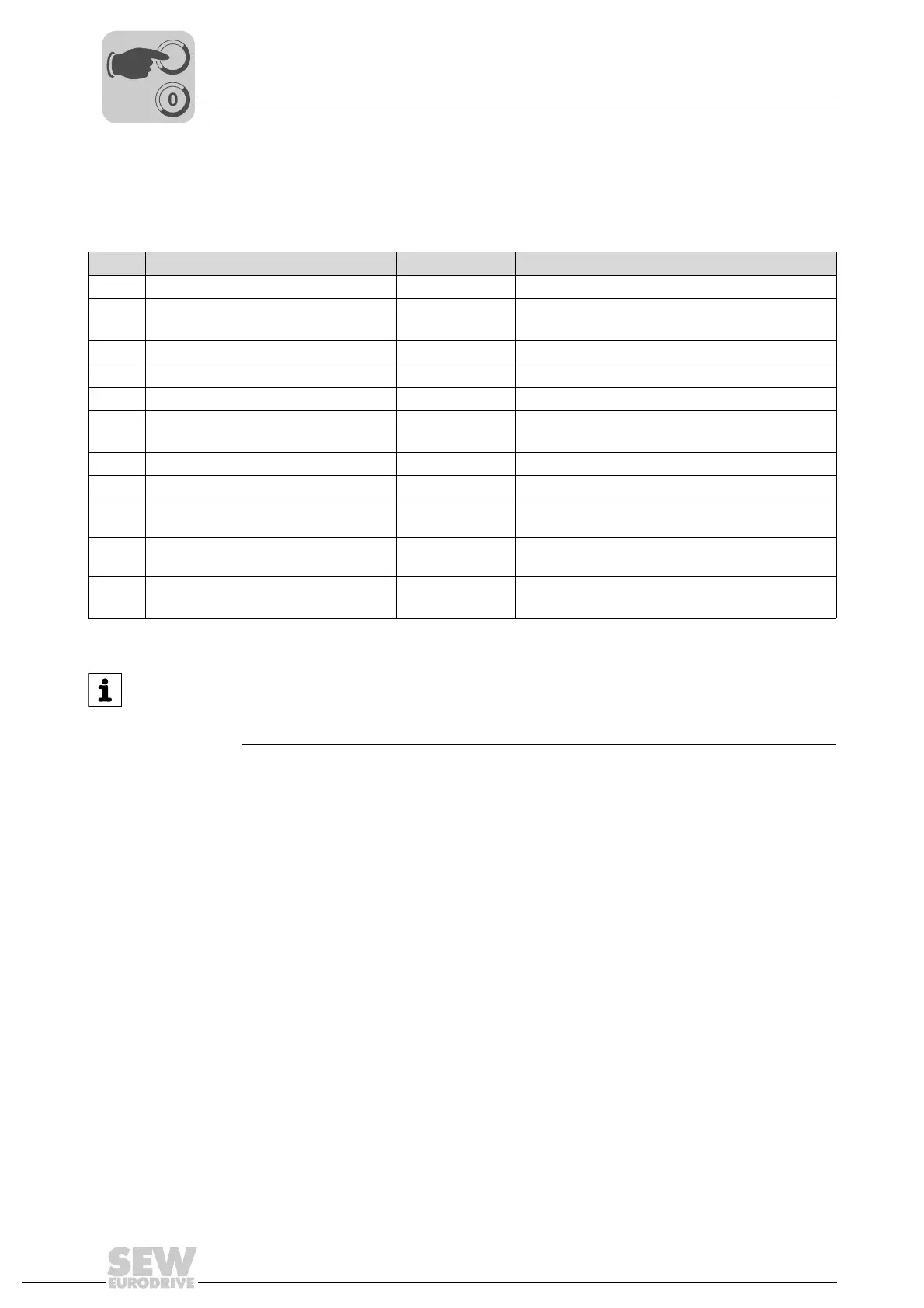
6.8.4 Monitoring parameters
The following table shows the monitoring parameters:
The parameter group 0 is used to display internal drive parameters for monitoring
purposes. You cannot change these parameters.
No. Name Display range Description
P0-03 Setpoint speed -500% – +500% Speed display (100% = nominal motor frequency)
P0-04 Setpoint speed -P1-01 – +P1-01
[Hz] or [rpm]
Speed display in Hz or rpm
P0-13 Output torque 0 - 200% Output torque (100% = nominal motor torque)
P0-20 DC link voltage [V DC] Internal DC link voltage
P0-21 Inverter temperature [°C] Temperature inside the unit
P0-25 Calculated rotor speed [Hz] or [rpm] Calculated motor speed
(only valid in a vector control mode)
P0-26 kWh counter 0.0 - 999.9 kWh Energy consumption in [kWh]
P0-27 MWh counter 0.0 - 60000 MWh Energy consumption in [MWh]
P0-28 Software ID, IO processor e.g. "1.00",
"493F"
Version number and check sum of the I/O
processor in the unit
P0-29 Software ID, motor control e.g. "1.00",
"7A5C"
Version number and check sum of the motor
controller in the unit
P0-30 Serial number of the inverter 000000 - 999999
00-000 - 99-999
Serial number of the unit
e.g. 540102 / 24 / 003
INFORMATION
In addition to the parameters described above, the keypad or the parameter menu
show other parameters. However, these are irrelevant for the drive, thus they are not
described here.