Doc# E166703 4-17
4: Electrical Installation
Electro Industries/GaugeTech
The Leader In Power Monitoring and Smart Grid Solutions
Electro Industries/GaugeTech
The Leader In Power Monitoring and Smart Grid Solutions
Electro Industries/GaugeTech
The Leader In Power Monitoring and Smart Grid Solutions
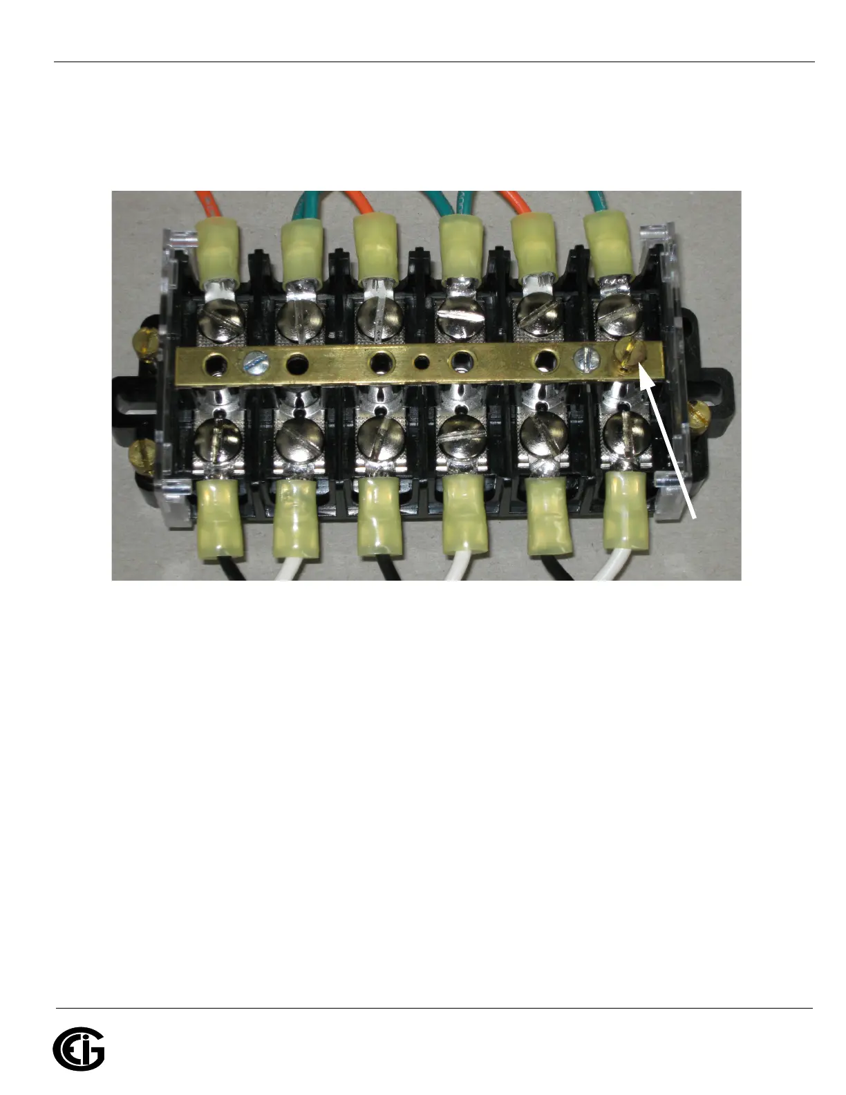
5. Remove one of the brass shorting screws from the plastic base and place it through
the brass shorting bar over one of the grounded terminals and tighten (max torque
of 16.2 in-lb, 1.8 N-m).
a. Verify that, when tightened, the screw head is in full contact with the brass bar.
Figure 4.6: EI SB-6TC with Shorting Screw Attached to Ground Terminal
6. Remove another brass shorting screw and place it through the brass bar over an
un-grounded lead of a CT and tighten (max torque of 16.2 in-lb, 1.8 N-m).
a. Verify that, when tightened, the screw head is in full contact with the brass bar.
7. If necessary, remove another brass shorting screw and place it through the brass
bar over an un-grounded lead of the second CT and tighten (max torque of 16.2 in-
lb, 1.8 N-m).
a. Verify that, when tightened, the screw head is in full contact with the brass bar.
8. If necessary, remove another brass shorting screw and place it through the brass
bar over an un-grounded lead of the third CT and tighten (max torque of 16.2 in-lb,
1.8 N-m).
a. Verify that, when tightened, the screw head is in full contact with the brass bar.
SHORTING
SCREW
ATTACHED TO
GROUND