54
Power source
A
(*1)
B
CPU
Input
CT input
C
D
E
G
F
OUT1
Ground terminal
Insulated
Insulated Insulated Insulated
Communication (*2)
Non-insulated
Insulated
Transmission
output
Non-insulated
Set value memory
number external
selection (*2)
Non-insulated
Insulated Insulated
Insulated
Insulated
Insulated
Non-insulated
Insulated
Heater burnout
alarm output
OUT2, A2,
LA or P24
output
A1 output
A3 output
A4 output
External operation
External setting input
PD control
Proportional band (P) : 0.1 to 999.9%
Derivative time (D) : 0 to 3600sec (off when set to 0)
Proportional cycle : 1 to 120sec
Reset :
Proportional band converted value
Thermocouple, RTD input: –199.9 to 999.9
( )
DC input: –1999 to 9999 (The placement of the decimal
point follows the selection.)
Output high/low limit : 0 to 100% (DC current output: –5 to 105%)
ON/OFF control
Hysteresis : Thermocouple, RTD input: 0.1 to 100.0
( )
DC input: 1 to 1000 (The placement of the decimal point
follows the selection.)
Supply voltage : 100 to 240V AC, 50/60Hz, 24V AC/DC, 50/60Hz
Allowable voltage fluctuation : 100 to 240V AC : 85 to 264V AC
24V AC/DC : 20 to 28V AC/DC
Ambient temperature : 0 to 50
(32 to 122 )
Ambient humidity : 35 to 85%RH (non-condensing)
Power consumption : Approx. 15VA
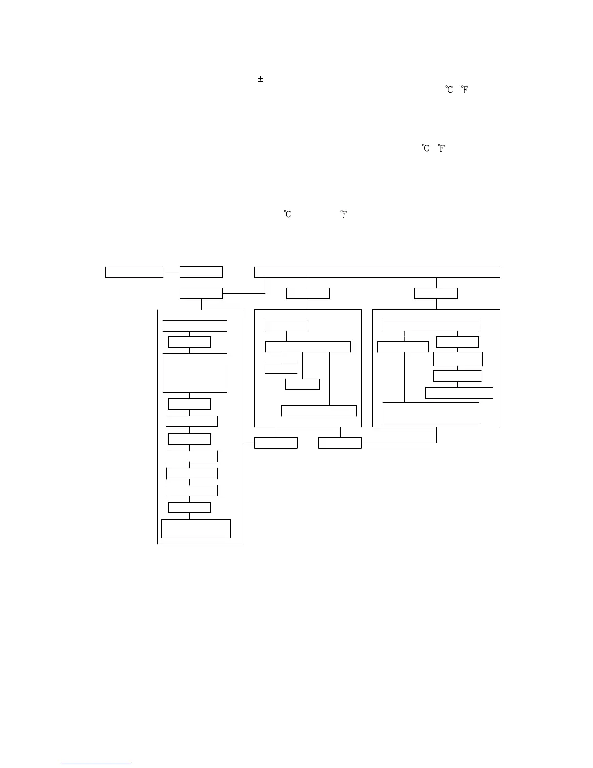
Circuit insulation configuration
(*1) When both OUT1 and OUT2 are DC current output type or Non-contact voltage
output type, A is not electrically insulated from B.
(*2) When OUT1 is DC current output type or Non-contact voltage output type,
A is not electrically insulated from F, and A is not electrically insulated from G.
When OUT2 is DC current output type or Non-contact voltage output type,
B is not electrically insulated from F, and B is not electrically insulated from G.