System Configuration
38 ATM60 / ATM90 / KHK53
Dec 2021
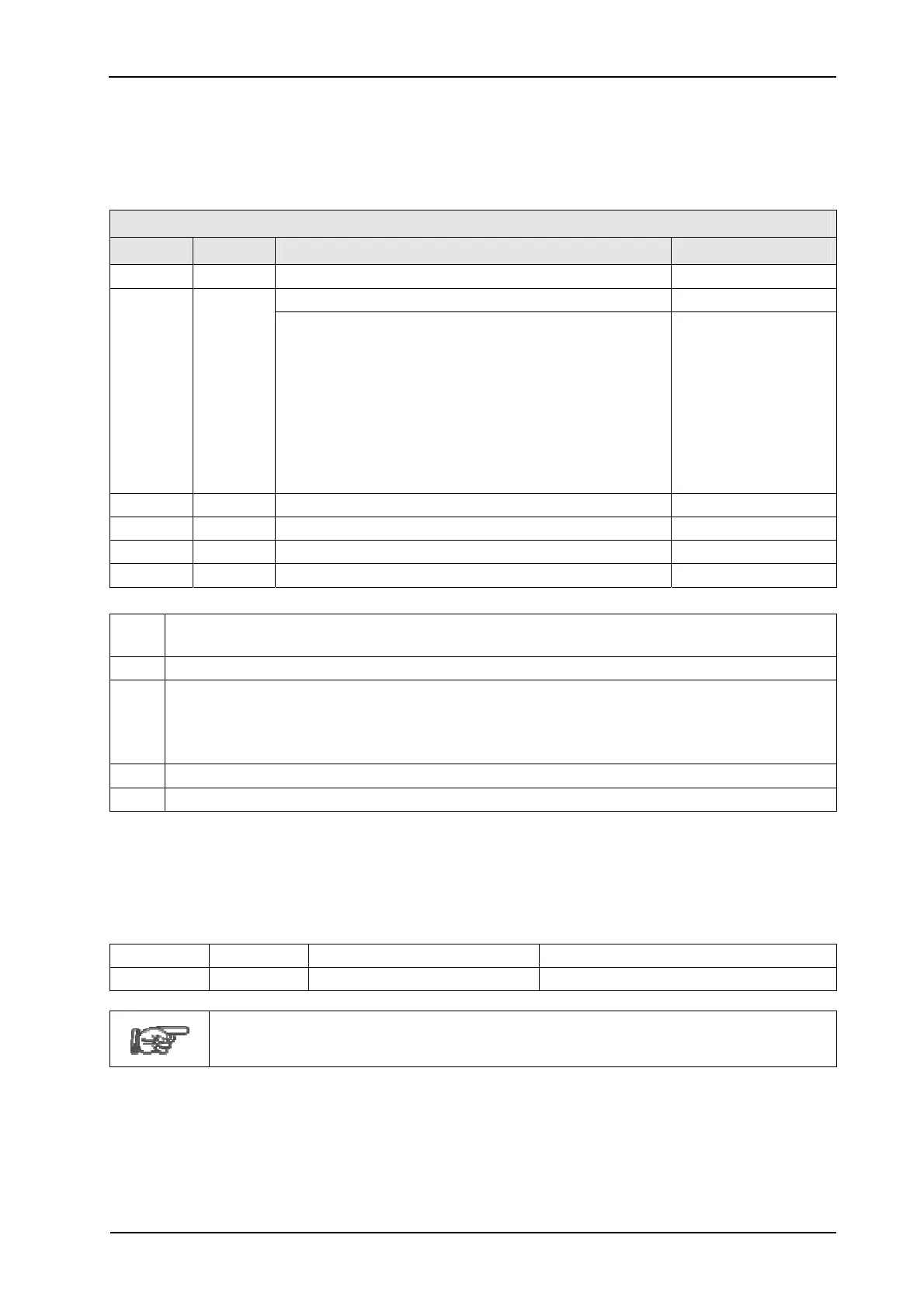
8.3.2 Device-Specific Data
Allocation
and content of this data (octet-8..n) are predefined via the GSD file and can be
changed by projecting. Format and content are checked after receipt of the complete telegram
by the application software.
Service DDLM_SET_Prm
Octet Type Explanation Value (Default)
8 BYTE
Spec_User_Prm_BYTE
(x1)
[00]h
9 BYTE Operating mode [0E]h
Bit 7
Selection node address source
(m1)
0
Bit 6
Activation of the 'SSA' service
(m1)
0
Bit 5..4 Reserved 0
Bit 3 Scaling function (ON, OFF). 1
(p1)
Bit 2
Commissioning diagnostics control
(m2)
1
(p1)
Bit 1 Class 2 functionality (ON, OFF). 1
Bit 0 Code sequence (0: ascending, 1: de-
scending)
0
10..11 UINT16 Measuring units per rev. (CPR). -- (31-16) [00.00]h
(p2)
12..13 UINT16 Measuring units per rev. (CPR). -- (15-00) [20.00]h
(p2)
14..15 UINT16 Total measuring range (CMR). -- (31-16) [20.00]h
(p2)
16..17 UINT16 Total measuring range (CMR). -- (15-00) [00.00]h
(p2)
(x1)
Defines the system behaviour of the DP_Controller ASIC. – Not adjustable in the con-
fig. tool.
(m1)
Manufacturer-specific function. – Not defined in the encoder profile.
(m2)
Value has no meaning for ATM60-P/ATM90-P rotary encoders. Function is always en-
abled.
For linear encoders of the
KHK53-P type, the function is optionally adjustable (default
setting = enabled (1)) – see following pages.
(p1)
For the ATM90-P
, the functions of bit 1 and bit 2 are interchanged.
(p2)
Device-dependent – see below.
8.3.3 Operating Mode
8.3.3.1 Code Sequence
Definition of the counting direction for the position value:
0 CW clockwise ascending Default setting
1 CCW counter-clockwise ascending
Setting per telegram is only possible if setting by hardware via DIP switch S1-(8)
is OFF.
The view to determine the counting direction is device-dependent:
For the ATM90-P: looking at the baseplate; for the ATM60-P: looking at the shaft; and for the
KHK53-P: beginning from the first measuring element (X0001).