Encoder – Mounting and Connection
62 ATM60 / ATM90 / KHK53
Dec 2021
10.3.6 Linear Encoder KHK53 w
ith Bus Link Adapter – Cable Fitting
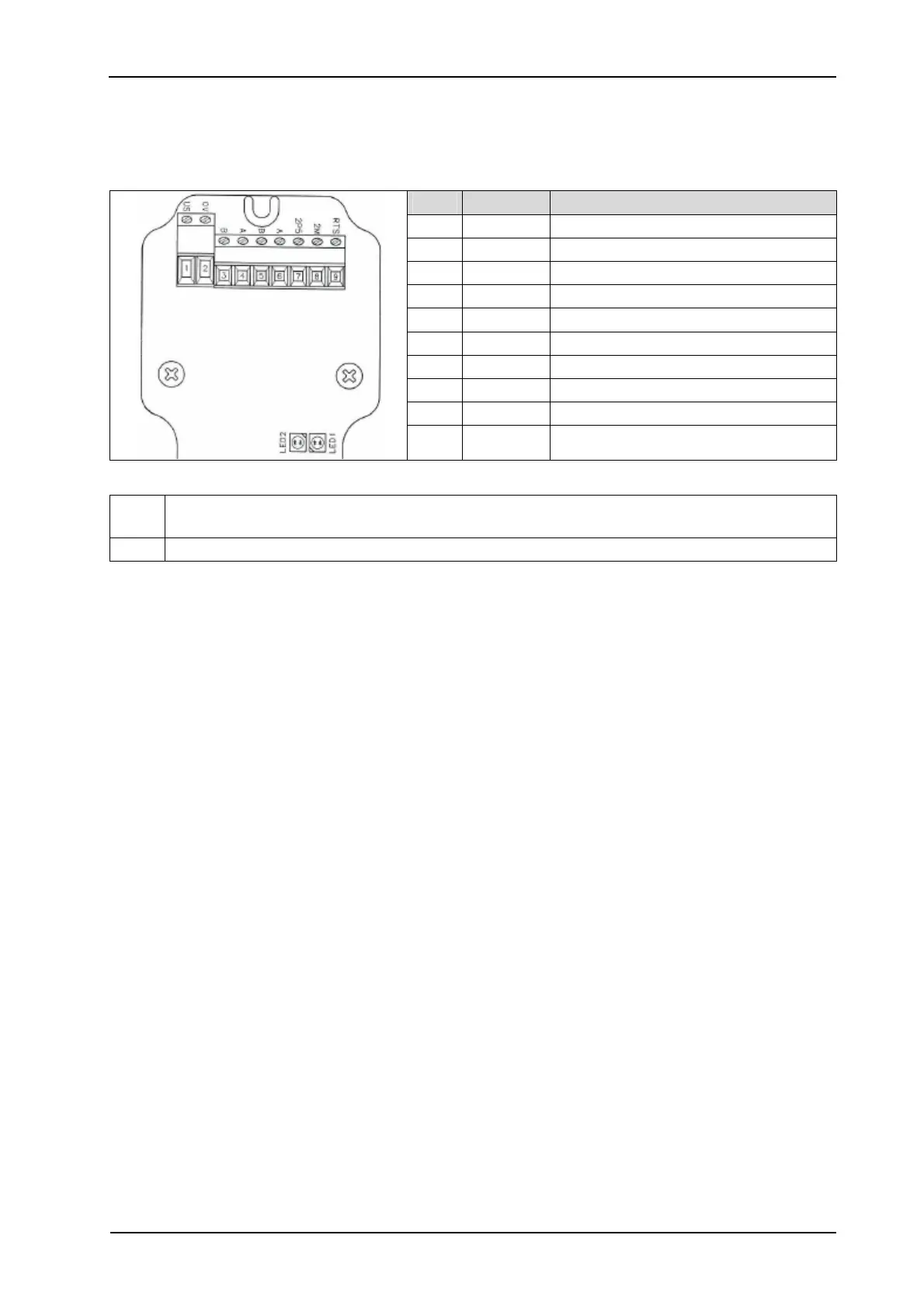
KHK53 with bus link adapter – connection via 3 cable fittings. The electrical wiring is via the in-
ternal terminal block (X1).
X1 Signal Description
1 US (24V) Operating voltage 10-32 V
2 GND 0 V (Gnd)
3 B B line ProfiBus DP (out)
4 A A line ProfiBus DP (out)
5 B B line ProfiBus DP (in)
6 A A line ProfiBus DP (in)
7 2P5 +5 V (potential separated)
(1)
8 2M 0 V (potential separated)
(1)
9 RTS Request to Send
(2)
Figure 10–7: Pinout Linear Encoder KHK53 with Bus Link Adapter
(1)
For external bus termination or supplying the transmitter/receiver of a fibre-optic con-
nection.
(2)
Signal is optional, serves to detect the direction of a fibre-optic connection.
10.4 Device Handling in the Network
The following encoder features are configured via the hardware:
• Station address (node ID).
• Counting direction.
• Bus termination.
• Preset function.
The following measures are required to execute one of these functions (model-dependent):
• Remove screw cap on the back of the bus link adapter housing (ATM
60 with cable fitting or
screw-in system M12).
• Remove screw cap on the front of the encoder housing (ATM 90 with screw-in system M14).
• Pull off bus link adapter housing (ATM 90 with bus link adapter/KHK53 with bus link
adapter).