Encode
Mountin
and Connection
Dec 2021
ATM60 / ATM90 / KHK53 59
10.3.3 ATM 60 w
ith Bus Link Adapter – Screw-in System M12
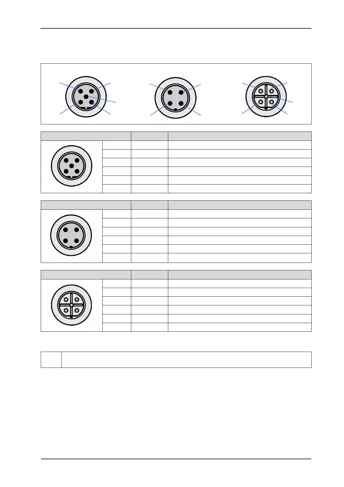
ATM 60 with bus link adapter – connection via 3 x screw-in system M12.
Profibus DP (IN) US Profibus DP (OUT)
Profibus DP (IN) Signal Description
1 nc
2 A A line Profibus DP
3 nc
4 B B line Profibus DP
5 Screen Housing potential
US Signal Description
1 US (24V) Operating voltage (10-32) V
2 nc
3 GND 0 V (ground)
4 nc
Profibus DP (OUT) Signal Description
1 2P5 +5 V (potential separated)
(1)
2 A A line Profibus DP
3 2M 0 V (potential separated)
(1)
4 B B line Profibus DP
5 Screen Housing potential
Figure 10–4: Pinout ATM 60 Direct with Bus Link Adapter – Screw-in System M12.
(1)
For external bus termination or supplying the transmitter/receiver of a fibre-optic con-
nection.
1
5
43
2
2
5
3
4
1
2
3
4
1