Encode
Mountin
and Connection
Dec 2021
ATM60 / ATM90 / KHK53 63
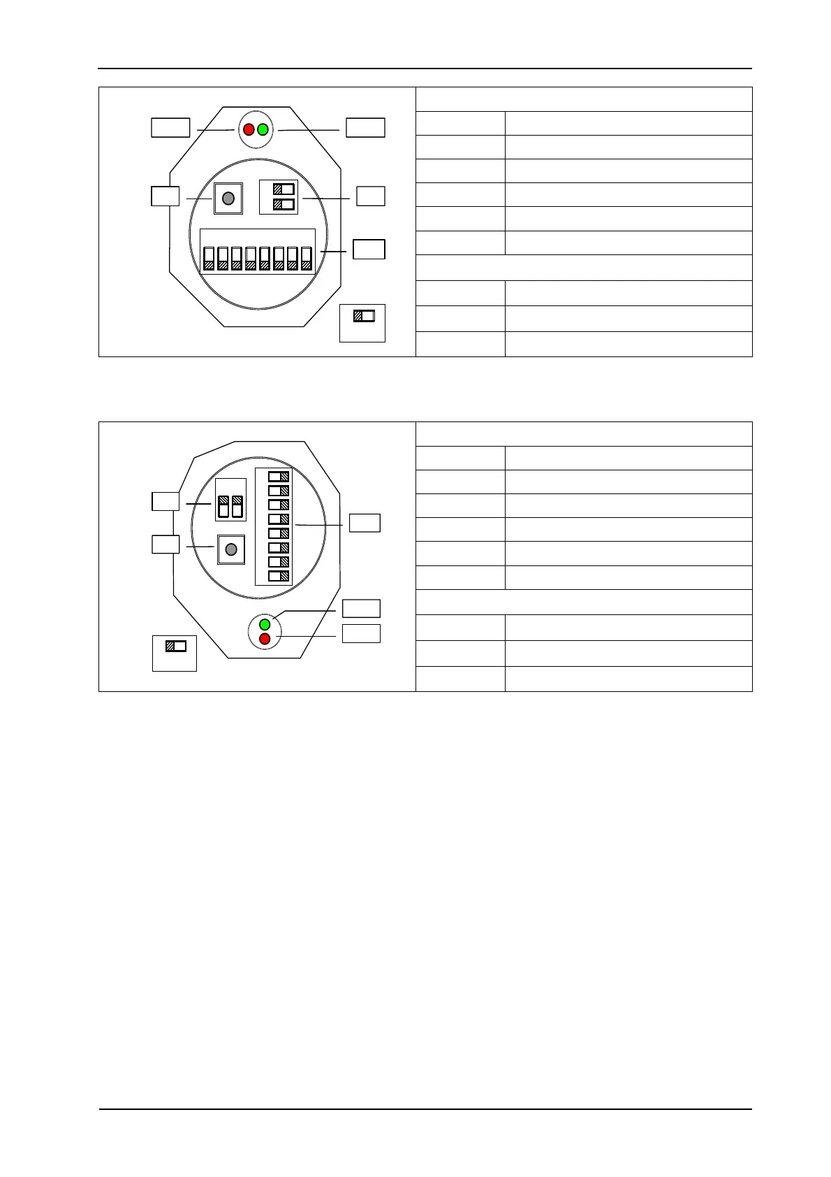
Switch settings
S 1 (7-1) Address setting (0..127)
S 1 (8-8) Counting direction (CW/CCW)
S 2 Bus termination
S 3 Preset pushbutton (number SET)
Status information
LED-1 Operating voltage (green)
LED-2 Bus activity (red)
S 3
S 1
S 2
OFF ON
87
4321
2
1
LED-2 LED-1
Figure 10–8: Device Handling in the Network 'ATM 60' (DIP Switch in the Bus Link
Adapter).
Switch settings
S 1 (7-1) Address setting (0..127)
S 1 (8-8) Counting direction (CW/CCW)
S 2 Bus termination
S 3 Preset pushbutton (number SET)
Status information
LED-1 Operating voltage (green)
LED-2 Bus activity (red)
S 2
S 1
S 3
OFF ON
8
7
6
5
4
3
2
1
2
1
LED-2
LED-1
Figure 10–9: Device Handling in the Network 'ATM 90' (Aperture for DIP Switch in the
Encoder).
In the version with a bus link adapter (ATM 90), the switches S1 and S2 are also inside the bus
link adapter.