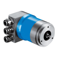
Encode
Parameters/Attributes
Dec 2021
ATM60 / ATM90 / KHK53 25
6.2 Data Storage
The profile-specific operating parameters of the encoder are generally saved in an EEPROM.
Since, for Profibus DP, the parameter data (DDLM_Set_Prm) is re-transmitted for each start,
there will be only partial storage in the EEPROM.
The following data is stored in the EEPROM.
Parameter Function
"Offset value"
"Preset value"
Preset button was pressed or the number of the 'Preset value' was
changed via the Protocol, to set a new position value.
Operating mode Giving the address setting (EEPROM/switch). -- DDLM_Set_Prm.
Node ID Giving the address. -- DDLM_Set_Slave_Adr.
Storing the encoder parameters in the EEPROM.
The time for storage depends on the data length (8 bytes, blockwise) and is 10 ms
approx. per
parameter.
The measurement-specific operating parameters of the encoder system are defined by the
manufacturer, and are stored in the EEPROM. This data is read out within the initialisation
phase (power-on) by the EEPROM, and checked for validity. A faulty data set is replaced by its
corresponding default value. Simultaneously, an appropriate ID is set within the error flag
(alarm). -- see also 9.4.3.
6.3 Encoder Attributes/Parameters
6.3.1 Fundamental Explanations
The properties (attributes) can be configured via a configuration tool or set to a default value by
the manufacturer.
The values are needed to define the behaviour of the encoder (producing or using process
data). This description only shows the typical (basic) attributes supported by an encoder, with-
out reference to the configuration via the field bus protocol. – Further information see (Parame-
terisation 8.3).
• All parameter values with position details must lie within the overall working
area which, at the time, is defined by the CMR value.
• If several parameters are changed online, there may be secondary effects.
The user needs to take this into account.
6.3.2 Counting Direction/Code Sequence
This attribute defines whether ascending or descending position values are output when the en-
coder shaft rotates clockwise (CW) or counter-clockwise (CCW), looking at the shaft end.

 Loading...