Encoder – Mounting and Connection
64 ATM60 / ATM90 / KHK53
Dec 2021
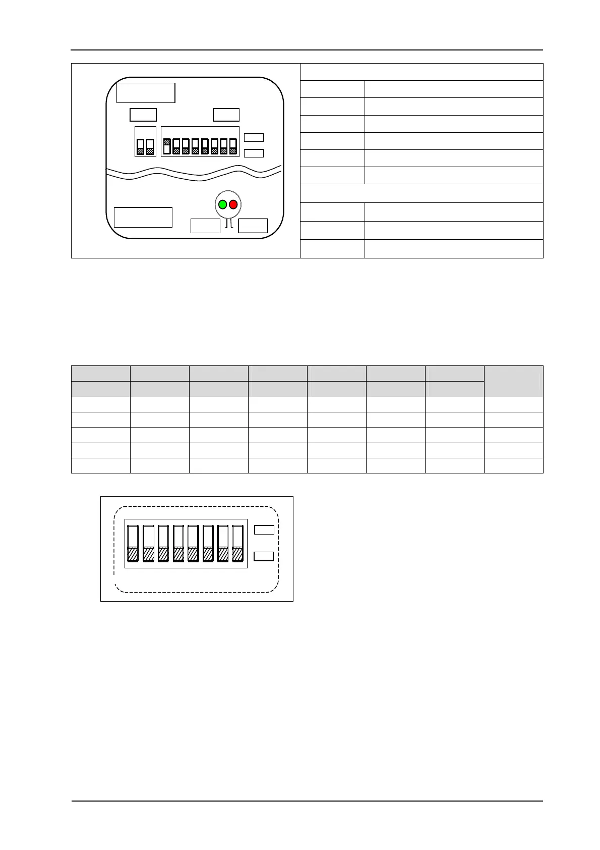
Switch settings
S 1 (7-1) Address setting (0..127)
S 1 (8-8) Counting direction (CW/CCW)
S 2 Bus termination
Status information
LED-1 Operating voltage (green)
LED-2 Bus activity (red)
LED-1 LED-2
S 1S 2
OF
ON
87
32121
Back Side
Front Side
Figure 10–10: Device Handling in the Network 'KHK53' (DIP Switch in the Bus Link
Adapter).
10.4.1 Address Setting
The station (node) address (NODE ID) can be set using DIP switch S1 (7-1). The factory setting
(default) is "1". The address must not be the same as for another subscriber in the network.
DIP-7 DIP-6 DIP-5 DIP-4 DIP-3 DIP-2 DIP-1
2
6
(msb) 2
5
2
4
2
3
2
2
2
1
2
0
(lsb)
Address
0 0 0 0 0 0 0 0
0 0 0 0 0 0 1 1
... ... ... ... ... ... ... ...
1 1 1 1 1 1 0 126
1 1 1 1 1 1 1 127
OF
ON
87654321
Figure 10–11: DIP Switch S1 Setting
DIP