- 73 -
2. Digital Output Unit Output Unit
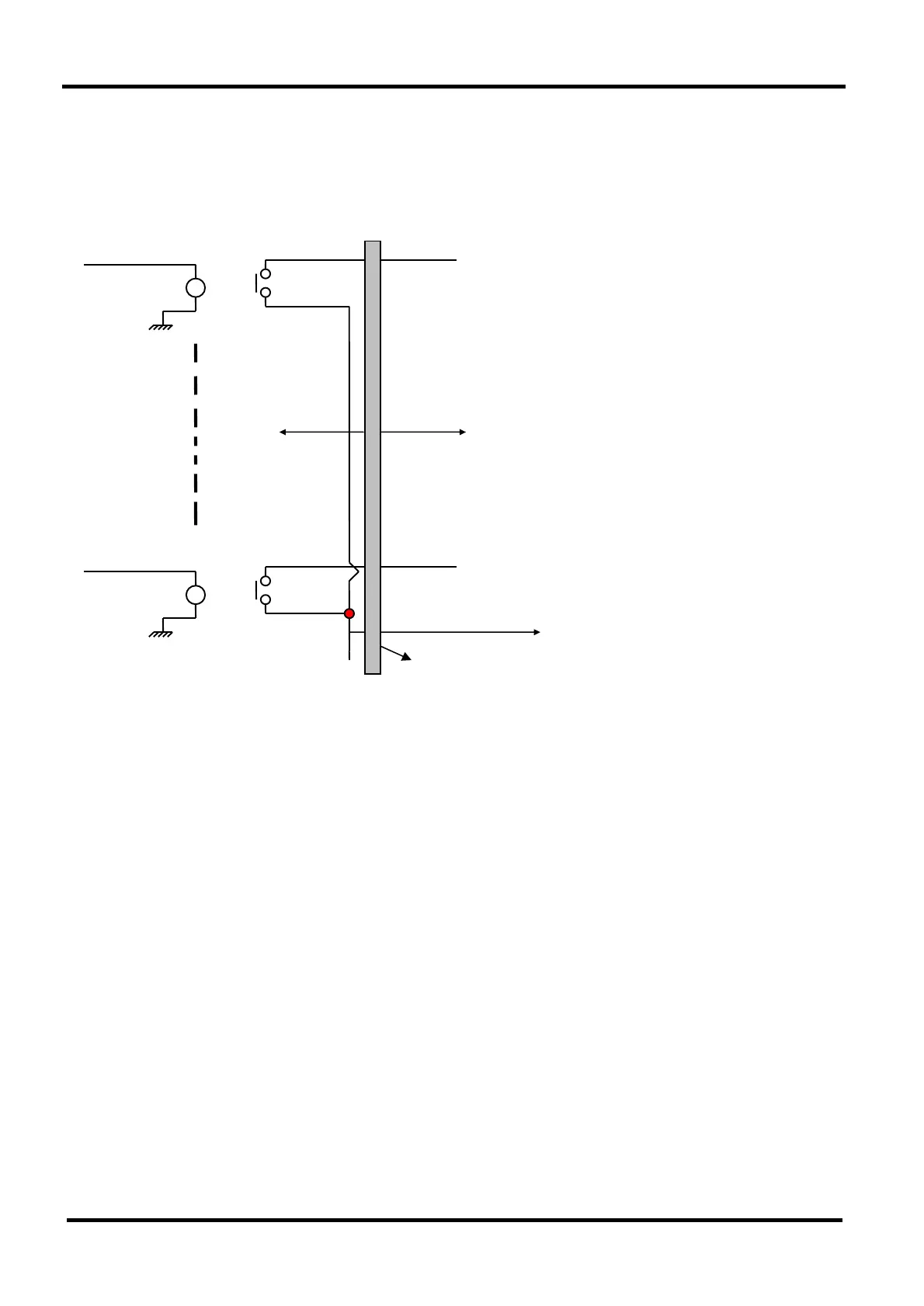
● Output scheme of Relay-Contact Type
Control 1 TB 1 CONTACT OUTPUT: OUT #1
Coil 1 CONTACT 1
UNIT INSIDE UNIT OUTSIDE
Control 8 TB 8 CONTACT OUTPUT: OUT #8
Coil 8 CONTACT 8
TB 9 COMMON (per 8CH )
D/O UNIT TERMINAL BOX
1. This D/O unit offers one common terminal per 8 relay outputs.
2. Therefore, output comes through contact point of relay of channel, which
voltage is active (On) that is linked to common terminal box shown in the
scheme as above.
● ! Caution: Connection of D/O
-. Because capacity of relay’ s contact point is 1 ampere that is used to this
D/O unit, outside appliances must to be checked their capacities whenever
they operate via relay.
If the capacity is exceeded, it must be used via Buffer Relay.
-. As this unit’ s common terminal is approved at maximum DC 48 volt and AC
250 volt, capacity must not be exceeded.
-. When this D/O unit’ s output is connected directly to solenoid valve or relay,
make sure that relay’ s coil is adhered to inverse direction diode and
solenoid valve coil is adhered to serge absorber necessarily.

 Loading...


