56
8012428/YWL2/3-0/2016-08| SICKO P E R A T I N G I N S T R U C T I O N S | DUSTHUNTER T
Subject to change without notice
3 ASSEMBLY AND INSTALLATION
3.3.7 Fitting the interface and I/O module (option)
Plug Interface modules and module carriers for I/O modules onto the hat rail in the MCU
(see “Component layout in the MCU (without purge air supply, with options)”, page 50) and
connect to the associated connection on the processor board with the line with plug con-
nector (see “MCU processor board connections”, page 51). Then plug the I/O modules on
the module carriers.
Connect the Interface modules using the customer provided network line to the local
network. Use the terminals on the module carrier to connect I/O modules.
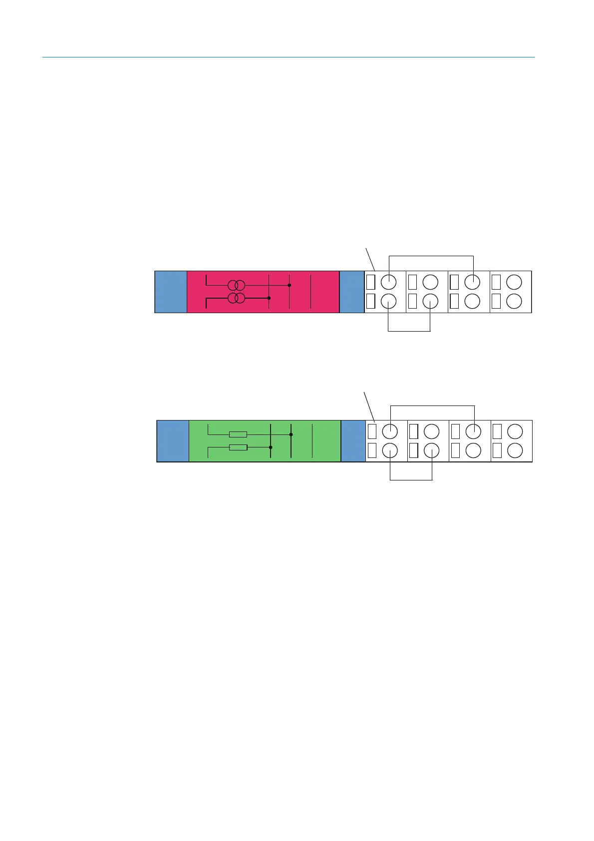
Terminal assignment of AO module
Fig. 33: Terminal assignment of analog output module
Terminal assignment of AI module
Fig. 34: Terminal assignment of analog input module
+
1
AO1
+
2
AO2
Shield
11
12
13
14
21
22
23
24
AO 1
+-
AO 2
+-
Module carrier
+
1
AI1
11
12
13
14
21
22
23
24
+
2
AI2
Shield
AI 1
AI 2
+-
Module carrier
 Loading...


