61
8012428/YWL2/3-0/2016-08| SICK O P E R A T I N G I N S T R U C T I O N S | DUSTHUNTER T
Subject to change without notice
START-UP AND PARAMETER SETTINGS 4
4.2 Application-specific settings
The measuring system must first be set to the respective internal duct diameter to ensure
correct measurement. The following steps are then necessary:
● Focussing the sender light beam
The light spot on the reflector must lie within the optical active reflection surface under
consideration of the active measuring path and the swivel angle allowed.
● Scaling the measuring system to a path free of particles
Influences on measuring results specific to the device and dependent on the distance
must be eliminated. The path free from particles must be identical to the active
measuring path (distances between the optical interfaces of the sender/receiver unit
and reflector must be the same).
4.2.1 Preparatory work
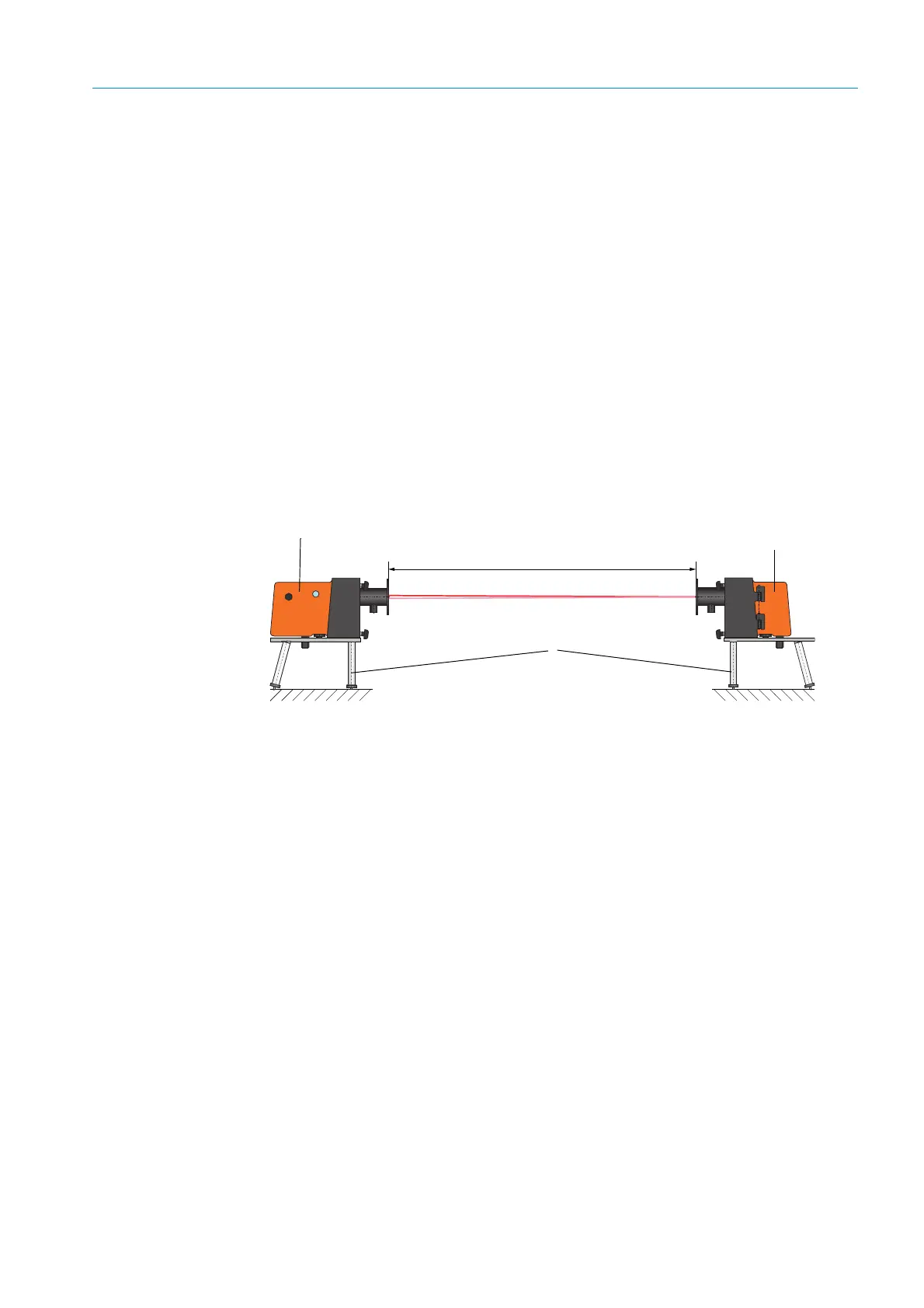
▸ Assemble the measuring system away from the measuring location at a dark place with
as little dust as possible where voltage supply is available.
There are two options:
– Using the optional adjusting stand (see “Miscellaneous”, page 125)
Fig. 35: Assembly on a dust-free path with adjusting stands (shown for DUSTHUNTER T100)
The reflector on DUSTHUNTER T50 must be placed in the bracket of the adjusting stand
according to Fig. “Assembly of the DHT-R5x reflector on the adjusting stand”.
Sender/receiver unit
Reflector
Adjusting stand
A
A =distance flange - flange
 Loading...


