77
8012428/YWL2/3-0/2016-08| SICK O P E R A T I N G I N S T R U C T I O N S | DUSTHUNTER T
Subject to change without notice
START-UP AND PARAMETER SETTINGS 4
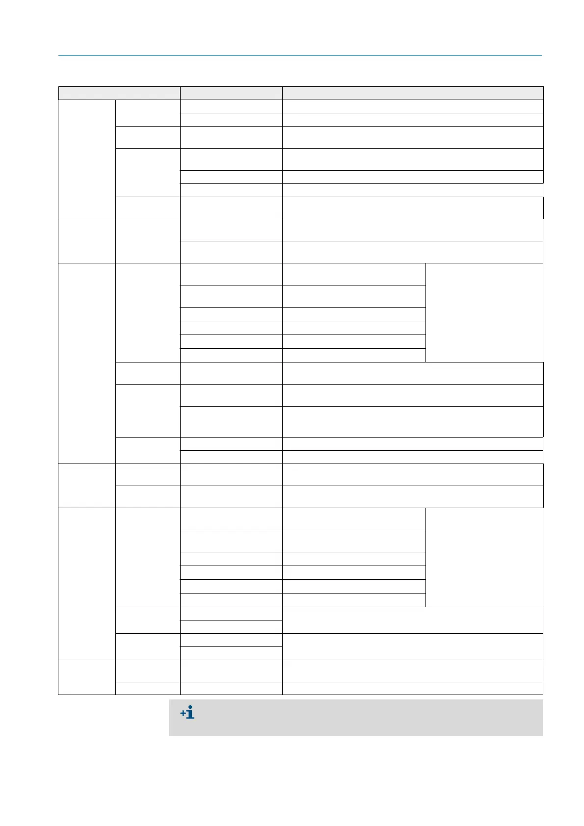
Field Parameter Remark
Analog Out-
puts
- General
Configuration
Output Error
current
Yes Error current is output.
No Error current is not output.
Error Current Value < Live Zero (LZ)
or > 20 mA
mA value to be output in “Malfunction” state (error case) (size
depends on connected evaluation system).
Current in main-
tenance
User defined value During “Maintenance”, the value entered in the “Maintenance cur-
rent” field is output.
Value measured last The value measured last is output during “Maintenance”
Measured value output The current measured value is output during “Maintenance”.
Maintenance
current
Whenever possible, value
≠ LZ
mA value to be output in “Maintenance” state
Optional Ana-
log Output
Modules
Use first analog
output module
Inactive Not permitted for DUSTHUNTER T100/T200 (results in error, because
AO 2 and AO 3 are available by default).
Active Opens the fields to set parameters for AO 2 and AO 3 (standard on
DUSTHUNTER T100 and T200)
Analog Out-
put 1
Parameter
Value on analog
output 1
Concentration a.c. (ext) Dust concentration under operating
conditions (based on extinction)
The selected measured vari-
ables are output on the ana-
log output.
Concentration s.c. (ext) Dust concentration under standard
conditions (based on extinction)
Opacity
Extinction
Transmission
Rel. opacity
Relative opacity
Live zero Zero point
(0, 2 or 4 mA)
Select 2 or 4 mA to ensure being able to differentiate between mea-
sured value and switched off device or interrupted current loop.
Output checkcy-
cle results on
the AO
Inactive Control values (see “Function check”, page 13) are not output on the
analog output.
Active Control values are output on the analog output (the “Output control
values at AO” checkbox in the “Adjustment / Function Check - Auto-
matic” directory must be activated).
Write absolute
value
Inactive Positive and negative measured values are differentiated.
Active The amount of the measured value is output.
Analog Out-
put 1 Scaling
Range low Lower measuring range
limit
Physical value at live zero
Range high Upper measuring range
limit
Physical value at 20 mA
Limiting Value Limit value Concentration a.c. (ext) Dust concentration under operating
conditions (based on extinction)
Select the measured variable
for which a limit value is to be
monitored.
Concentration s.c. (ext) Dust concentration under standard
conditions (based on extinction)
Opacity
Extinction
Transmission
Rel. opacity
Relative opacity
Hysteresis type Percent Assignment of the value entered in the “Hysteresis value” field as rel-
ative or absolute value of defined limit value
Absolute
Switch at Value exceeded Define the switching direction
Underflow
Limit Switch
Parameters
Limit value Value The limit value relay switches when the value entered is overflown or
underflown.
Hysteresis Value Define a tolerance for resetting the limit value relay
Set the parameters for “Analog Output 2(3) Parameter” and “Analog Output 2(3)
Scaling” in the same manner as for “Analog Output 1 Parameter” and “Analog Output 1
Scaling”.
 Loading...


