3 PRODUCT DESCRIPTION
8011325/18IM/2020-07-02|SICK
OPERATING INSTRUCTIONS | ICR880/890
Subject to change without notice
By combining several cameras in one reading system, it is possible to record several sides
in one passage (multi-side reading).
3.4.1 Reading configuration
The camera identifies 1D/2D codes in lines with the aid of a CMOS line. The lines are
continuously written into an image memory at high frequency. A two-dimensional object
image is created by the continuous feed of the object on the conveyor system.
The camera system cannot detect any codes on stationary objects.
A moving 1D/2D code on the object is reproduced as a grayscale matrix in the image
memory.
To decode the codes, contrast variations on the image are evaluated. The threshold can
be adapted to the ambient conditions. For faster evaluation, the evaluation range can be
restricted perpendicularly to the conveyor direction (code position).
3.4.2 Object trigger control
The camera system needs a suitable signal (trigger) to start a read process. As standard,
the start signal is issued via an external read-cycle sensor (photoelectric sensor). As soon
as an object has passed the read-cycle sensor, a time window (“internal reading gate”) is
opened in the camera system for the read process.
Alternatively, a command triggers the read process via a data interface or the
CAN-SENSOR network.
3.4.3 Focus control
For dynamic focusing (focus control), the camera needs continuous information about the
distance to the object surface. External sensors for measured value acquisition, such as
volume measurement systems and light grids, supply this information. The information
from the sensors is processed by the controller unit and forwarded to the camera
systems.
3.4.4 Illumination control
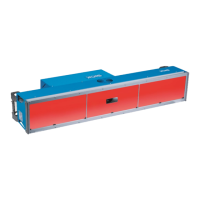
To be captured by the camera, the area to be read must be illuminated by a powerful LED
illumination unit. Depending on the model, the illumination unit produces a narrow, red,
blue-white, white or blue illumination area.
Fig. 12: Diagram of illumination unit with illumination area
Multi-side reading
Note

 Loading...