ELECTRICAL INSTALLATION 5
8011325/18IM/2020-07-02|SICK
Subject to change without notice
OPERATING INSTRUCTIONS | ICR880/890
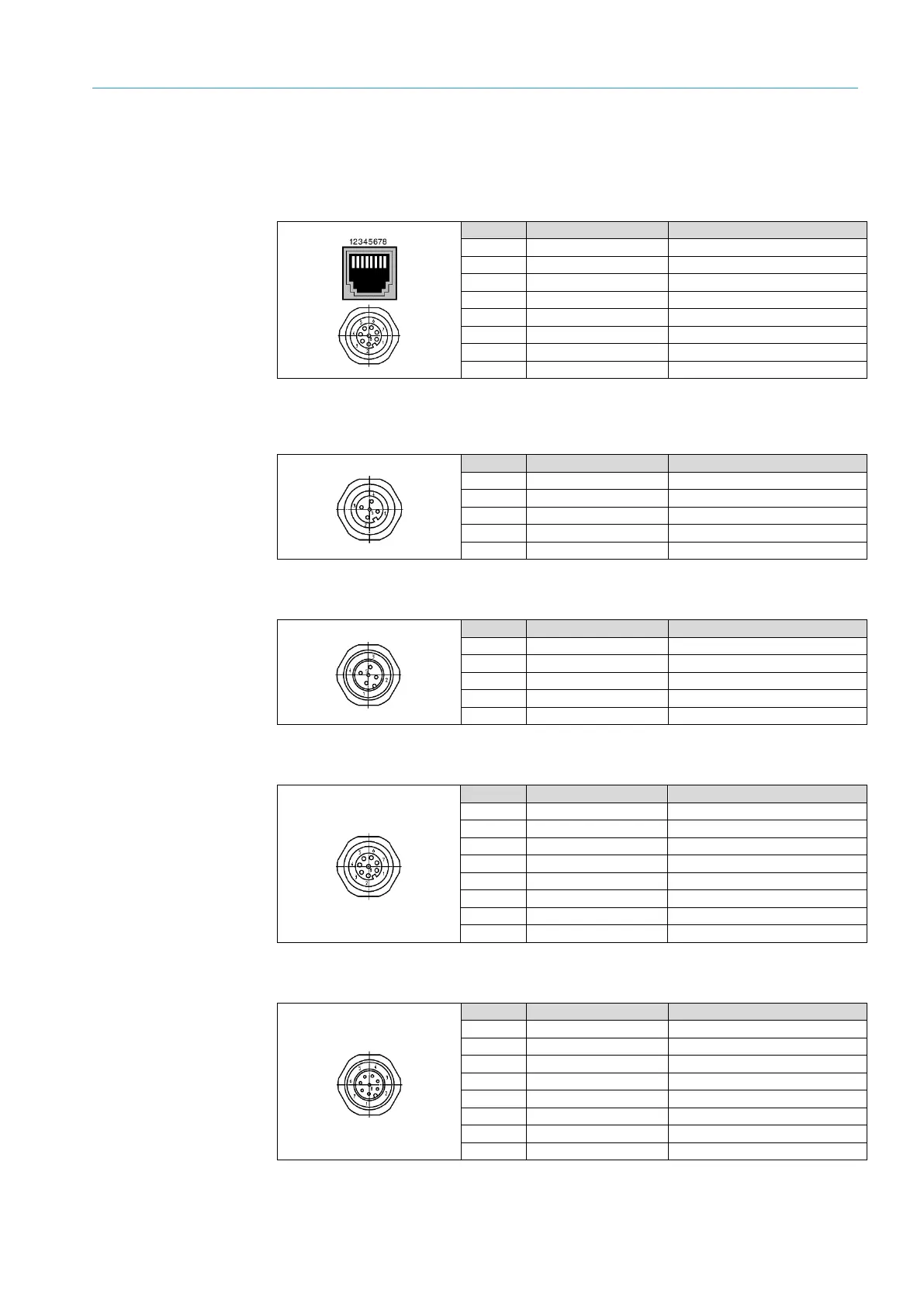
5.3.8 Pin assignment of the connecting cables
When delivered, all connections are equipped with protective caps.
“GBIT 1”/”GBIT 2”/“GBIT 3” connections (Ethernet, max. 1 Gbit/s)
Tab. 22: Pin assignment of the 8-pin RJ-45 female connectors/M12 “GBIT1”/“GBIT2”/“GBIT3”
plug connectors
“CAN 1-OUT” connections (CAN-SENSOR networks)
Tab. 23: Pin assignment of the 5-pin M12 “CAN 1-OUT” (A-coded) female connectors
“CAN 1-IN” connections (CAN-SENSOR networks)
Tab. 24: Pin assignment of the 5-pin M12 “CAN 1-IN” (A-coded) male connectors
“ILLUMINATION” connection (control data interface for illumination unit)
Tab. 25: Pin assignment of the 8-pin M12 “ILLUMINATION” (A-coded) female connector
“AUX” connection (auxiliary data interface)
Tab. 26: Pin assignment of the 8-pin M12 “AUX” (A-coded) male connector

 Loading...