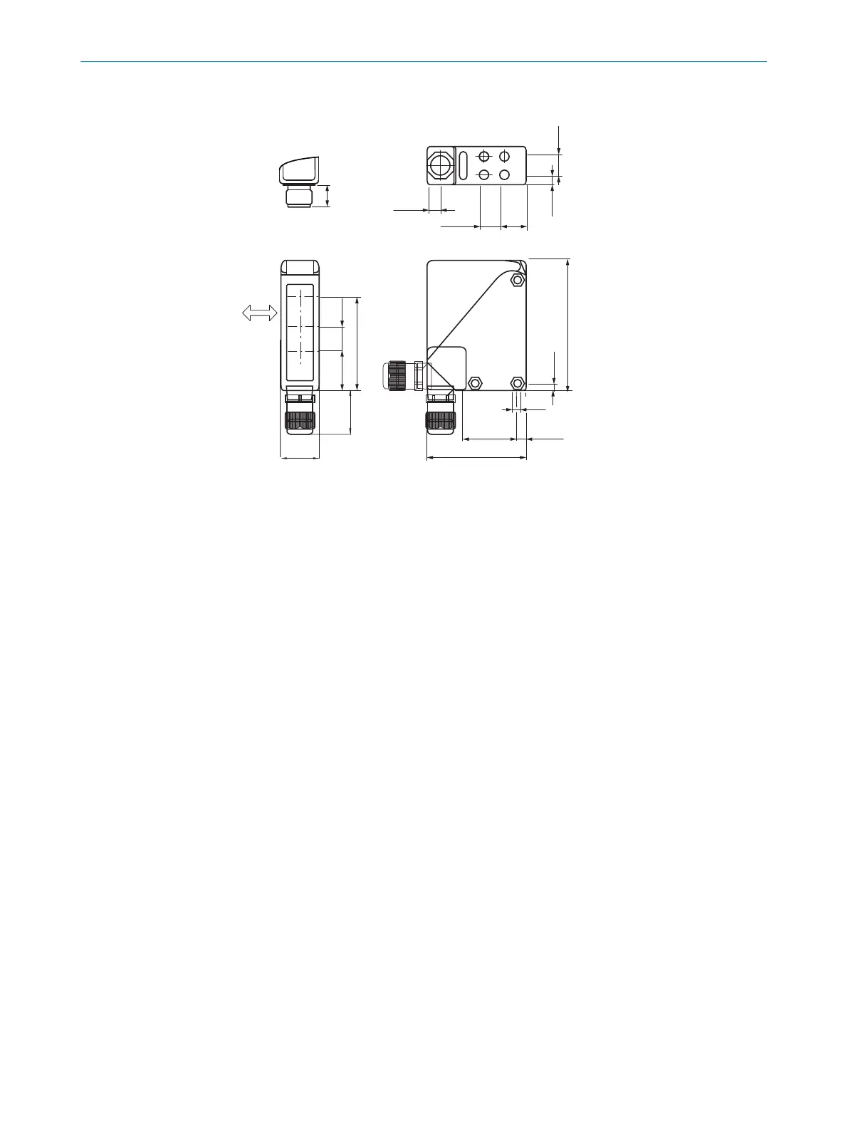
13.1 Dimensional drawing
6
1
2
7
8
27
(1.06)
max. 32
(1.26)
14
(0.55)
6.5
(0.26)
10.5
(0.41)
14
(0.55)
15.5
(0.61)
70 (2.76)
M5
6.2
(0.24)
30 (1.18)
92 (3.62)
5
(0.20)
3
4
5
6
15
(0.59)
26
(1.02)
61 (2.40)
14,4
(0.57)
8
Figure 8: Dimensional drawing
1
Alignment sight
2
LED indicator yellow
3
Preferred direction of the target object
4
Center of optical axis / Sender
5
Center of optical axis / receiver at close range
6
Center of optical axis / receiver at long range
7
Mounting hole ø 5.5 mm, both sides for hexagon nut M5
8
M16 fitting or male connector can be rotated by 90°
TECHNICAL DATA 13
8009202.11O1 | SICK
Subject to change without notice
15

 Loading...


