EasyManuals Logo

SICK W34 Series User Manual

SICK W34 Series
133 pages
To Next Page IconTo Next Page
To Previous Page IconTo Previous Page
Page #7 background imageLoading...
Page #7 background image
NC = normally closed
NO = normally open
Q / Q = switching outputs
TE / Test = test input (see table 2 and Additional functions)
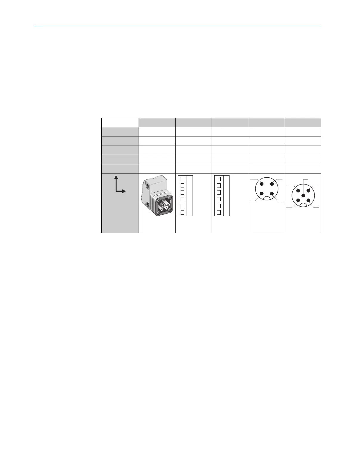
6.1 WT34-Bxxx, WT34-Vxxx
U
B
: 10 ... 30 V DC, see "Technical data", page 14
Table 2: DC
WT34- B3x3 B2x0 V2x0 B4x0 V5x0
1 + (L+) + (L+) + (L+) + (L+) + (L+)
2 - (M) - (M) - (M) Test Test
3
Q/Q
- Alarm - (M) - (M)
4 -
Q/Q Q/Q Q/Q Q/Q
5 - Test Test - Alarm
I
N
= 4 A
1 2 3 4 5
0.14 ...
1.5 mm
2
I
N
= 4 A
1 2 3 4 5
0.14 ...
1.5 mm
2
I
N
= 4 A
1
2
4 3
1
2
5
4 3
ELECTRICAL INSTALLATION 6
8009202.11O1 | SICK
Subject to change without notice
7

Table of Contents

Questions and Answers:

Question and Answer IconNeed help?

Do you have a question about the SICK W34 Series and is the answer not in the manual?

SICK W34 Series Specifications

General IconGeneral
BrandSICK
ModelW34 Series
CategoryAccessories
LanguageEnglish

Related product manuals