Explicaciones relativas al esquema de conexión (tablas, capitolo 71.1 y véase "WT34-
Rxxx", página 81):
Alarma = salida de alarma (véase tabla 52 y Funciones adicionales)
n.c. = no conectado
NC = contacto normalmente cerrado
NO = contacto normalmente abierto
Q/Q = salidas conmutadas
TE/Test = entrada de prueba (véase tabla 52 y Funciones adicionales)
71.1
WT34-Bxxx, WT34-Vxxx
U
B
: 10 ... 30 V CC, véase "Datos técnicos", página 87
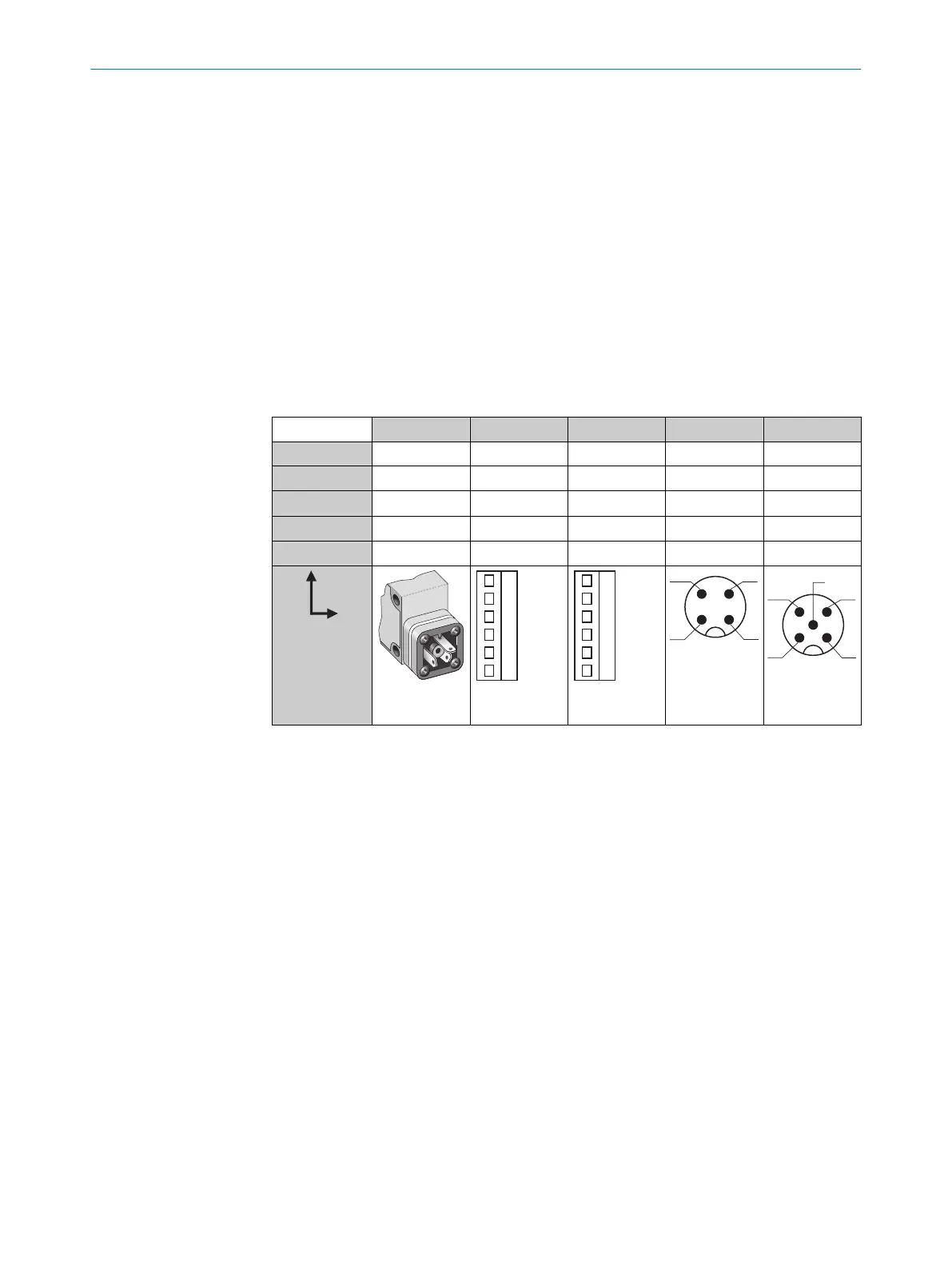
Tabla 52: CC
WT34- B3x3 B2x0 V2x0 B4x0 V5x0
1 + (L+) + (L+) + (L+) + (L+) + (L+)
2 - (M) - (M) - (M) Test Test
3
Q/Q
- Alarma - (M) - (M)
4 -
Q/Q Q/Q Q/Q Q/Q
5 - Test Test - Alarma
I
N
= 4 A
0,14 ...
1,5 mm
2
I
N
= 4 A
0,14 ...
1,5 mm
2
I
N
= 4 A
71 INSTALACIÓN ELÉCTRICA
80
8009202.11O1 | SICK
Subject to change without notice

 Loading...


