2
Potentiometer: adjust‐
ment of the sensing
range
3
Switch: light (L) / dark
(D)
4
Switch: NPN / PNP
5
Potentiometer: adjust‐
ment of time delay t
2
6
Potentiometer: adjust‐
ment of time delay t
1
7
Potentiometer: adjust‐
ment of time stage
2
Potentiometer: adjust‐
ment of the sensing
range
3
Switch: light (L) / dark
(D)
4
Switch: NPN / PNP
2
Potentiometer: adjust‐
ment of the sensing
range
3
Switch: light (L) / dark
(D)
4
Potentiometer: adjust‐
ment of time delay t
2
5
Potentiometer: adjust‐
ment of time delay t
1
6
Potentiometer: adjust‐
ment of time stage
2
Potentiometer: adjust‐
ment of the sensing
range
3
Switch: light (L) / dark
(D)
5 Mounting
Mount the sensor using a suitable mounting bracket (see the SICK range of acces‐
sories).
Note the sensor’s maximum permissible tightening torque of 2 Nm.
Note the preferred direction of the object relative to the sensor, cf. see "Dimensional
drawing", page 15.
6 Electrical installation
The sensors must be connected in a voltage-free state. The following information must
be observed, depending on the connection type:
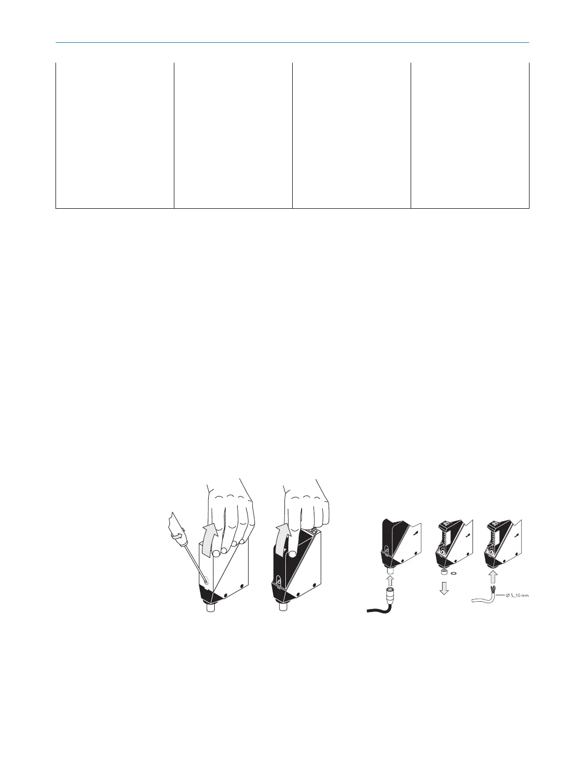
– Plug connection: note pin assignment: when the cover is open, the male connector
can be swiveled horizontally and vertically.
– Terminal connection: note the permissible cable diameter of 5 to 10 mm. When
the cover is open, the M16 fitting can be swiveled horizontally and vertically.
Unscrew the M16 fitting and remove sealing plug. Lead voltage-free supply cable
through and connect sensor in accordance with table 2 and table 4. Retighten
M16 fitting with seal so that the IP enclosure rating of the device is ensured.
Figure 1: Opening the sensor Figure 2: Electrical connection
Only apply voltage/switch on the power supply once all electrical connections have
been established.
Explanations of the connection diagram (tables, chapter 6.1 and see "WT34-Rxxx",
page 8):
Alarm = alarm output (see table 2 and Additional functions)
n. c. = not connected
5
MOUNTING
6
8009202.11O1 | SICK
Subject to change without notice

 Loading...


