Connection
6.3 Connecting the reader
SIMATIC MV500
122 Operating Instructions, 03/2021, C79000-G8976-C494-05
Table 6- 3 Industrial Ethernet connecting cable M12 (male, 4-pin) / M12 (male, 4-pin)
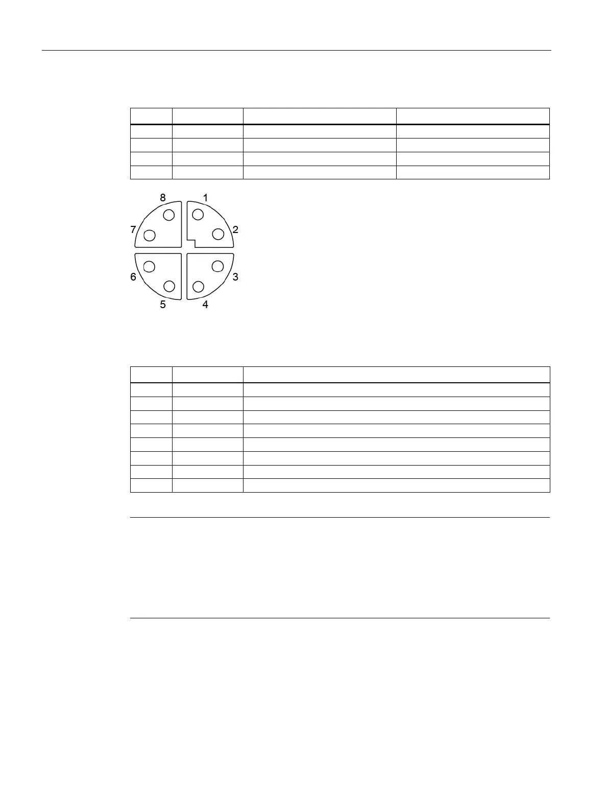
Figure 6-5 Pin assignment of "X2 LAN2" Ethernet socket (M12, 8-pin) ②
Table 6- 4 Industrial Ethernet connecting cable M12 (male, 8-pin) / M12 (male, 8-pin)
Cable assembly for connection to IE RJ45
interface
To connect the "X2 LAN2" interface (M12, 8
-pin) with an IE RJ45 interface, you need to
replace one of the M12 connectors of the cable "6XV1878
-5Gxxx" with the IE connector FC
-1BB12-2AA0"). For strain relief to be guaranteed, you need to enlarge the
assembled cable to a length of approx. 5
- 10 cm behind the replaced connector using an
 Loading...