Installation and Startup
5-5
PROFIBUS Optical Bus Terminal (OBT)
C79000-G8976-C122-02
Instructions for Connectoring Plastic Fiber–Optic Cables (with photos)
You can download a detailed instruction brochure with photos illustrating how to
connector plastic fiber–optic cables from the Internet:
S German: http://www.ad.siemens.de/csi/net
S English: http://www.ad.siemens.de/csi_e/net
Select SEARCH on this page and enter the number 574203 in the Entry ID box
and start the search.
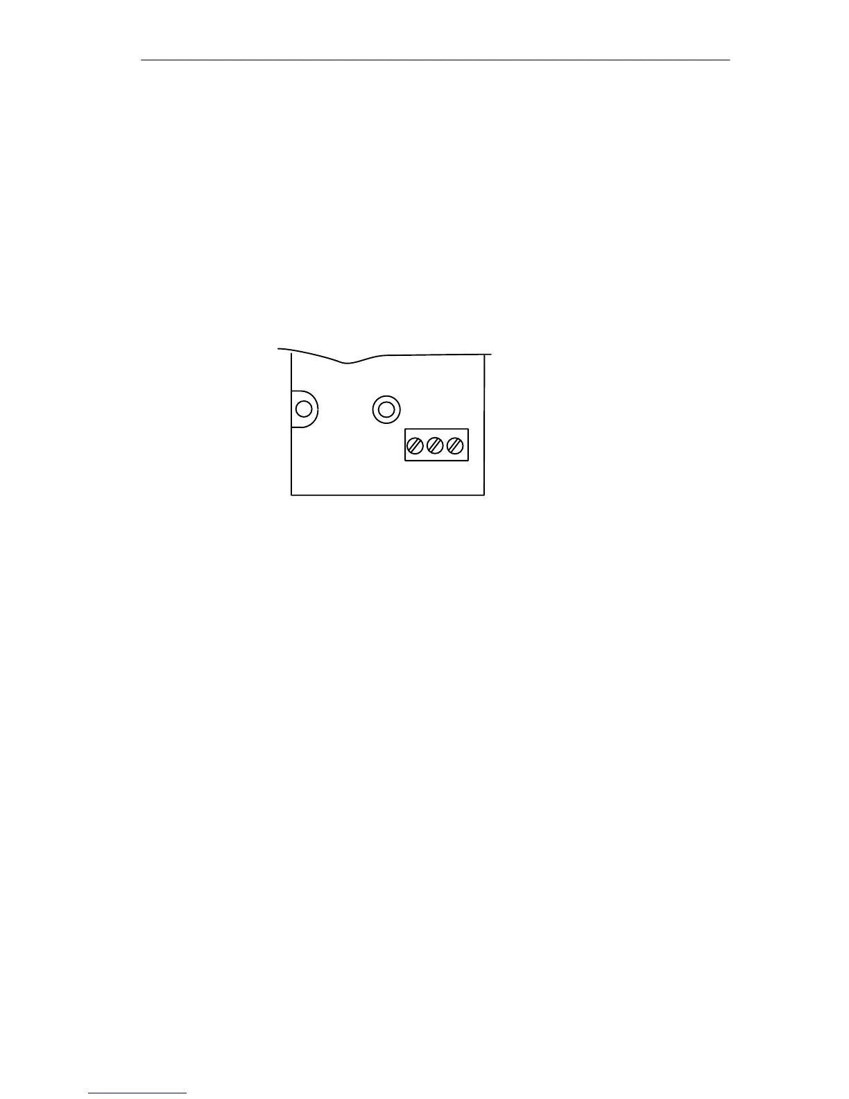
Connecting the Power Supply
PE
M
L+
NEC CLASS2
24VDC, 200 mA
Figure 5-3 Layout of the Terminal Block – Ground Terminal PE and Power Supply
Terminals M, L+
S The power supply for the PROFIBUS OBT must be a stabilized safety extra-low
voltage complying with IEC 950 / VDE 0805, minimum +18 V and maximum
+32 V (typically +24 V). The power source must meet the specifications of NEC
class 2 to comply with the UL/CSA approval. The unit is intended to be installed
on the load side of the class 2 or class 3 power source as defined by the
National Electric Code (NEC), Article 725–2
The module must be wired correctly according to the National Electrical code
(NEC) complying with NEC Article 725–52, 725–54, 725–61 and 725–71.
S If the PROFIBUS OBT is not installed on a grounded rail, a grounding
conductor with a cross-section of 2.5 mm
2
should be connected from the PE
terminal to the nearest possible ground point.