Digital modules
3.21 Digital output module SM 322; DO 16 x UC 24/48 V; (6ES7322-5GH00-0AB0)
S7-300 Automation System Module data
Manual, 08/2006, A5E00105505-04
3-63
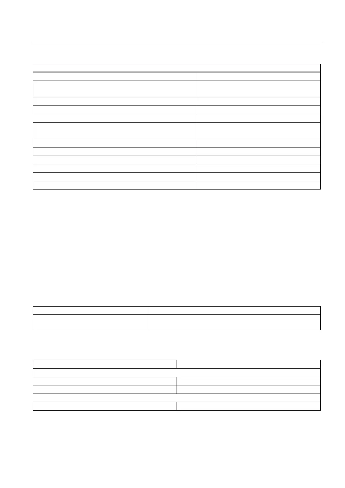
Dimensions and weight
Output delay (resistive load)
• at "1" to "0"
• at "1" to "0"
max. 6 ms
max. 3 ms
External fuse for relay outputs Fuse, I
2 t
:1 A
2
s, fast-blow fuse*
Lamp load max. 2.5 W
Internal parallel wiring of 2 outputs Varistor, 85 V
• for redundant load control
• for performance increase
supported
not supported
Control of a digital input supported
Switching frequency
• with resistive load
max. 10 Hz
• with inductive load to IEC 947-5-1; DC 12 AC/12
max. 0.5 Hz
• with lamp load
max. 0.5 Hz
Wiring the actuators With 40-pin front connector
* Outputs must be protected by a 250 V fast-blow fuse (recommended fuses: Wickman 194-
1100 1.1 A and Littelfuse 0217-800 V 800 mA.)
When mounted in a hazardous area to National Electric Code (NEC), always remove the
fuse when the module is outside of the potentially explosive atmosphere, and use a suitable
tool.
3.21.1 Parameters of the digital output module SM 322 DO 16 x UC24/48 V
Programming
The tables below show data record numbers for static and dynamic parameters.
Table 3-14 Data record 0 (static parameters):
Parameters Comment
Enable diagnostics Enabling an interrupt as a reaction to module failure caused by faulty
parameter, hardware error, or voltage error.
Table 3-15 Data record 1 (dynamic parameters):
Parameters Comment
Reaction to CPU STOP
Hold last value
Substitution value output
Substitution value
Substitution value Each bit represents an output
This module supports fail state/substitution value outputs when the CPU changes from RUN
to STOP.

 Loading...


