Diagnostics data of signal modules
B.2 Structure and content of diagnostics data bytes 0 to 7
S7-300 Automation System Module data
B-2 Manual, 08/2006, A5E00105505-04
B.2 B.2 Structure and content of diagnostics data bytes 0 to 7
Introduction
The section below describes the structure and content of the various bytes in diagnostics
data. General rule: An error is indicated by a logic "1" at the relevant bit.
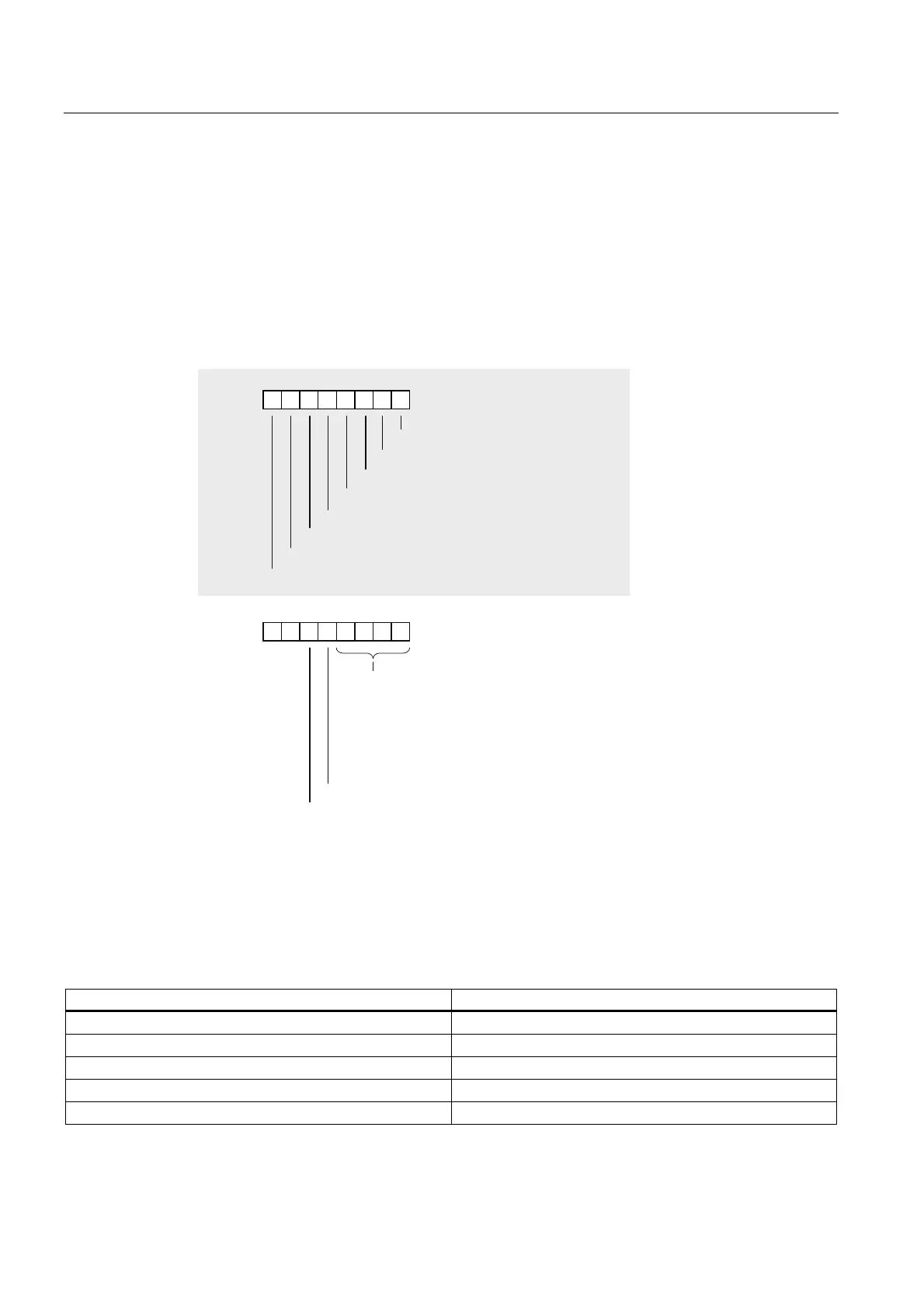
Bytes 0 and 1
0RGXOHSUREOHP
,QWHUQDOPDOIXQFWLRQ
([WHUQDOPDOIXQFWLRQ
&KDQQHOHUURUSUHVHQW
([WHUQDODX[LOLDU\VXSSO\PLVVLQJ
)URQWFRQQHFWRUPLVVLQJ
0RGXOHQRWSDUDPHWHUL]HG
,QFRUUHFWSDUDPHWHULQWKHPRGXOH
0RGXOHW\SH
&KDQQHOLQIRUPDWLRQDYDLODEOH
8VHULQIRUPDWLRQDYDLODEOH
%\WH
%\WH
&RGH
$QDORJPRGXOH
&38
)XQFWLRQPRGXOH
&3
'LJLWDOPRGXOH
Figure B-1 Bytes 0 and 1 of diagnostics data
Module classes
The table below lists the module class IDs (bits 0 to 3 in byte 1.)
Table B-1 Module class IDs
ID Module class
0101 Analog module
0110 CPU
1000 Function module
1100 CP
1111 Digital module